TB6562ANG
TB6562ANG is Dual Full-Bridge Driver manufactured by Toshiba.
TB6562ANG/AFG
TOSHIBA Bi-CMOS Integrated Circuit Silicon Monolithic
TB6562ANG/AFG
Dual Full-Bridge Driver IC for Stepping Motors
The TB6562ANG/AFG is a 2-phase bipolar stepping motor driver that contains DMOS transistors in the output stage. The driver achieves high efficiency through the use of low ON-resistance DMOS transistors and PWM current control circuitry.
Features
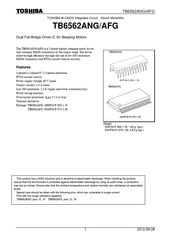
2-phase/1- 2-phase/W 1- 2-phase excitation PWM current control Power supply voltage: 40 V (max) Output current: 1.5 A (max) Low ON-resistance: 1.5 Ω (upper and lower transistors/typ.) Power-saving function Overcurrent protection: ILIM = 2.5 A (typ.) Thermal shutdown Package: TB6562ANG; SDIP24-P-300-1.78
TB6562AFG;...