Toshiba JDP2S05FS
UHF~VHF Band RF Switch Applications
| Part No. | JDP2S05FS |
|---|---|
| Datasheet | JDP2S05FS Download |
| Manufacturer |  Toshiba |
| Description | UHF~VHF Band RF Switch Applications |
| Buy | Stock & Price |
APPLICATIONS
●●
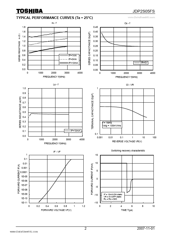
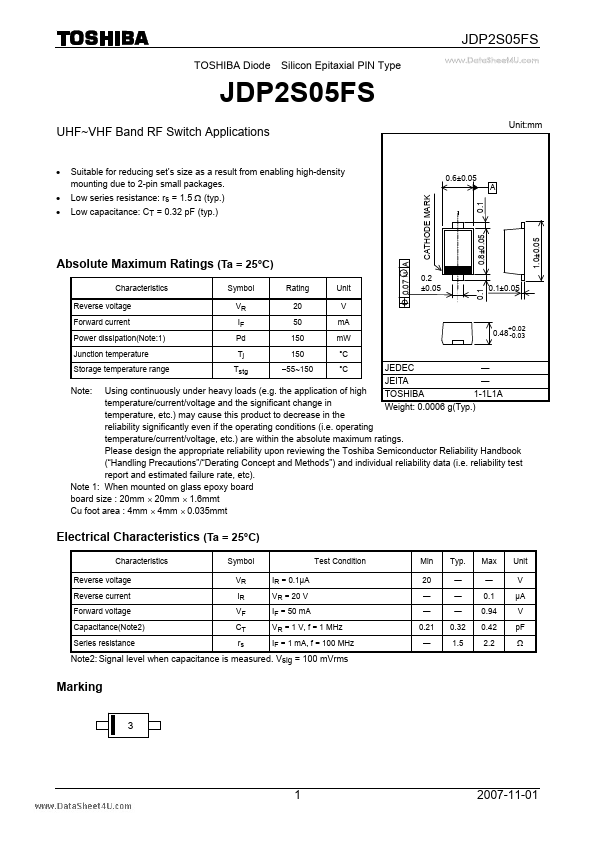
● Suitable for reducing set’s size as a result from enabling high-density mounting due to 2-pin small packages. CATHODE MARK Unit:mm 0.6±0.05 A 0.1 0.8±0.05 Low series resistance: rs = 1.5 Ω (typ.) Low capacitance: CT = 0.32 pF (typ.)
ABSOLUTE MAXIMUM RATINGS
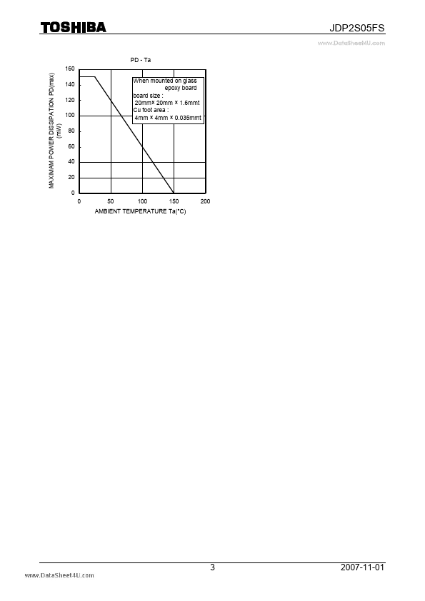
(Ta = 25°C) Characteristics Reverse voltage Forward current Power dissipation(Note:1) Junction temperature Storage temperature range Symbol VR IF Pd Tj Tstg Rating 20 50 150 150 −55~150 Unit V mA mW °C °C M 0.07 0.1 0.2 ±0.05 0.1±0.05 0.48 -0.03 +0.02 Using continuously under heavy loads (e.g. the application of high temperature/current/voltage and the significant change in temperature, etc.) may cause this product to decrease in the reliability significantly even if the operating conditions (i.e. operating temperature/current/voltage, etc.) are within the absolute maximum ratings. Please design the appropriate reliability upon reviewing the Toshiba Semiconductor Reliability Handbook (“Handling Precautions”/“Derating Concept and Methods”) and individual reliability data (i.e. reliability test report and estimated failure rate, etc).