Datasheet4U Logo Datasheet4U.com

TB62713N Datasheet 7 X 5 Dot Display Decoder And Driver

Manufacturer: Toshiba

Overview: 
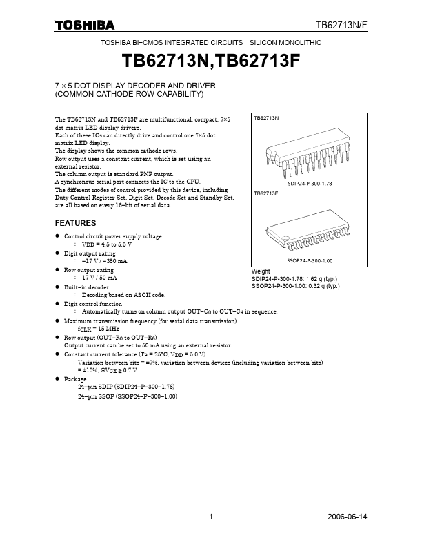
TB62713N/F TOSHIBA Bi−CMOS INTEGRATED CIRCUITS SILICON MONOLITHIC TB62713N,TB62713F 7 × 5 DOT DISPLAY DECODER AND DRIVER (MON CATHODE ROW CAPABILITY) The TB62713N and TB62713F are multifunctional, pact, 7×5 dot matrix LED display drivers. Each of these ICs can directly drive and control one 7×5 dot matrix LED display. The display shows the mon cathode rows. Row output uses a constant current, which is set using an external resistor. The column output is standard PNP output. A synchronous serial port connects the IC to the CPU. The different modes of control provided by this device, including Duty Control Register Set, Digit Set, Decode Set and Standby Set, are all based on every 16−bit of serial data.

This datasheet includes multiple variants, all published together in a single manufacturer document.

General Description

TB62713N/F PIN NUMBER 1 2 3 4 5~11 12 13 14 15, 16, 17, 19, 20 18 21 22 23 24 PIN NAME FUNCTION VDD DATA−IN (DI) 5 V power pin.

Serial data input pin.

CLOCK (CK) Clock input pin.

Key Features

  • Control circuit power supply voltage : VDD = 4.5 to 5.5 V Digit output rating :.
  • 17 V /.
  • 350 mA Row output rating : 17 V / 50 mA Built.
  • in decoder : Decoding based on ASCII code. Weight SDIP24-P-300-1.78: 1.62 g (typ. ) SSOP24-P-300-1.00: 0.32 g (typ. ) Digit control function : Automatically turns on column output OUT.
  • C0 to OUT.
  • C4 in sequence. Maximum transmission frequency (for serial data transmission) : fCLK = 15 MHz Row output (OUT.
  • R0 to OU.

TB62713N Distributor