TB67B054FTG Description
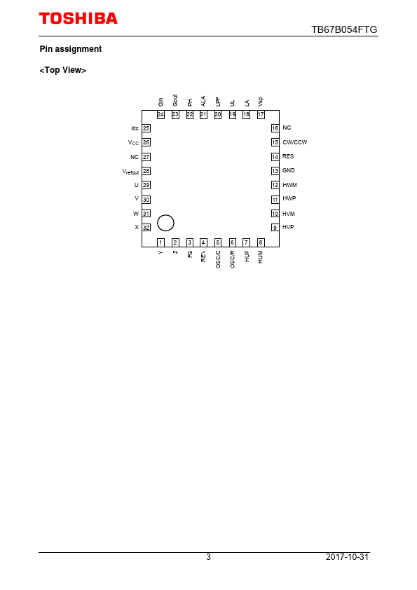
Symbol Function Description 5 OSC/C Oscillator capacitor CR oscillation 6 OSC/R Oscillator resistor 7 HUP Hall signal input, U 8 HUM 9 10 HVP HVM Hall signal input, V Gate block protection is activated when hall signals of U, V, and W phases are all “H” or “L”. These inputs have internal digital filters (≈ 500 ns) 11 HWP Hall signal input, W 12 HWM 13 GND Ground ― 14 RES Reset input L: Motor stops (mutation output...
TB67B054FTG Key Features
- Sine-wave PWM control
- Triangular-wave generator (carrier frequency = fosc/252 Hz)
- Lead angle control (0° to 58° in 32 separate steps)
- Current-limiting input pin
- Internal voltage regulator circuit (Vrefout = 5 V (typ.), 30 mA (max))
- Operating supply voltage range: VCC = 6 V to 16.5 V