DR65-0002
DR65-0002 is Linear Driver manufactured by Tyco Electronics.
Features n n n n n n n n
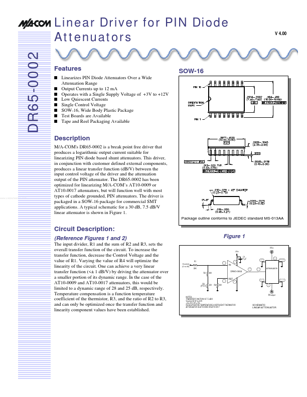
SOW-16
Linearizes PIN Diode Attenuators Over a Wide Attenuation Range Output Currents up to 12 m A Operates with a Single Supply Voltage of +3V to +12V Low Quiescent Currents Single Control Voltage SOW-16, Wide Body Plastic Package Test Boards are Available Tape and Reel Packaging Available
Description
M/A-'s DR65-0002 is a break point free driver that produces a logarithmic output current suitable for linearizing PIN diode based shunt attenuators. This driver, in conjunction with customer defined external ponents, produces a linear transfer function (d B/V) between the input control voltage of the driver and the attenuation output of the PIN attenuator. The DR65-0002 has been optimized for linearizing M/A-’s AT10-0009 or AT10-0017 attenuators, but will function well with most types of cathode grounded, PIN attenuators. The driver is packaged in a SOW-16 package for mercial SMT applications. A typical schematic for a 30 d B, 7.5 d B/V linear attenuator is shown in Figure 1.
Package outline conforms to JEDEC standard MS-013AA
..
Circuit Description
:
(Reference Figures 1 and 2)
The input divider, R1 and the sum of R2 and R3, sets the overall transfer function of the circuit. To increase the transfer function, decrease the Control Voltage and the value of R1. Varying the value of R4 will optimize the linearity of the circuit. One can achieve a very linear transfer function (<± 1 d B/V) by driving the attenuator over a smaller portion of its dynamic range. In the case of the AT10-0009 and AT10-0017 attenuators, this would be limited to a dynamic range of 28 and 25 d B, respectively. Temperature pensation is a function temperature coefficient of the thermistor, R3, and the ratio of R2 to R3, and can only be optimized once the transfer function and linearity ponent values have been established.
Figure 1
RFin +Vcc C1 .01 µF R1
14 4
2 1,3,4 16,14,13
Vcontrol (0 to 4V)
39K
12 7
ATTENNUATOR
R2 680
3 5
5,6,8
9,11,12
R3...