MAPCGM0003
MAPCGM0003 is S-Band Phase Shifter manufactured by Tyco Electronics.
Features
- -
- -
- -
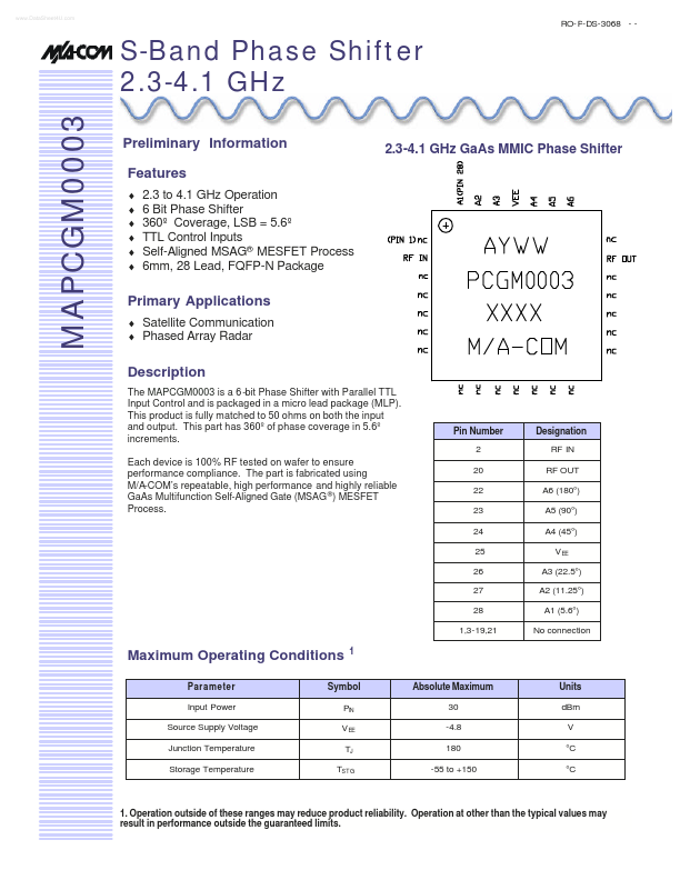
2.3-4.1 GHz Ga As MMIC Phase Shifter
2.3 to 4.1 GHz Operation 6 Bit Phase Shifter 360º Coverage, LSB = 5.6º TTL Control Inputs Self-Aligned MSAG® MESFET Process 6mm, 28 Lead, FQFP-N Package
Primary Applications
- Satellite munication
- Phased Array Radar
Description
The MAPCGM0003 is a 6 -bit Phase Shifter with Parallel TTL Input Control and is packaged in a micro lead package (MLP). This product is fully matched to 50 ohms on both the input and output. This part has 360º of phase coverage in 5.6º increments. Each device is 100% RF tested on wafer to ensure performance pliance. The part is fabricated using M/A-’s repeatable, high performance and highly reliable Ga As Multifunction Self-Aligned Gate (MSAG ®) MESFET Process.
Pin Number 2 20 22 23 24 25 26 27 28 1,3-19,21
Designation RF IN RF OUT A6 (180°) A5 (90°) A4 (45°) V EE A3 (22.5°) A2 (11.25°) A1 (5.6°) No connection
Maximum Operating Conditions
Parameter Input Power Source Supply Voltage Junction Temperature Storage Temperature
Symbol PIN V EE TJ TSTG
Absolute Maximum 30 -4.8 180 -55 to +150
Units d Bm V °C °C
1. Operation outside of these ranges may reduce product reliability. Operation at other than the typical values may result in performance outside the guaranteed limits.
RO- P-DS-3068
- - 2/7
S Band Phase Shifter Remended Operating Conditions
Characteristic Digital Supply Voltage Control Voltage Logic High Logic Low Junction Temperature TJ Symbol VEE A1 thru A6 3 0 5 0 5 Min -5.2 Typ -5.0
Max -4.8
Unit V
V V °C
0.4 150
Electrical Characteristics: TB = 25°C, Z0 = 50Ω , VEE = -5V
Parameter Bandwidth Insertion Loss Input VSWR (At Reference) Output VSWR (At Reference) RMS Phase Error RMS Phase Error
- Calibrated Phase Range Gain Variation over all Phase Shifter settings Digital Supply Current Input Third Order Intercept Input 1-d B pression Point Symbol f IL VSWR VSWR RMS RMS ?? ?G IEE ITOI P1d B Typical 2.3-4.1 6 1.5:1 1.2:1 6 3 360 <3 < 10 36 23 º º º d B m A...