SW-214 Datasheet Text
..
GaAs SPST Switch DC
- 3 GHz
Features q q q
SW-214
V2.00
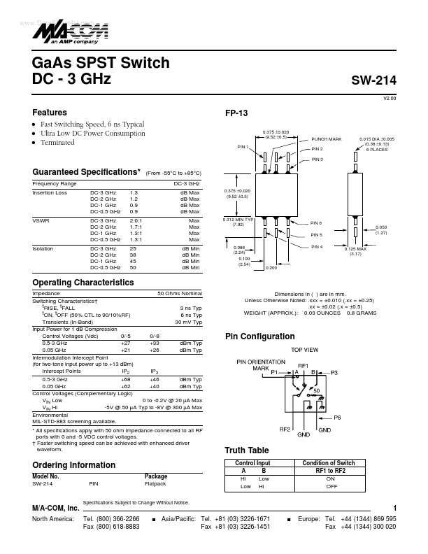
FP-13
0.375 ±0.020 (9.52 ±0.5) PIN 1 PUNCH MARK PIN 2 PIN 3 0.015 DIA ±0.005 (0.38 ±0.13) 6 PLACES
Fast Switching Speed, 6 ns Typical Ultra Low DC Power Consumption Terminated
Guaranteed Specifications-
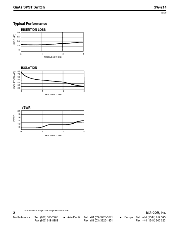
Frequency Range Insertion Loss DC-3 GHz DC-2 GHz DC-1 GHz DC-0.5 GHz DC-3 GHz DC-2 GHz DC-1 GHz DC-0.5 GHz DC-3 GHz DC-2 GHz DC-1 GHz DC-0.5 GHz 1.3 1.2 0.9 0.9 2.0:1 1.7:1 1.3:1 1.3:1 25 38 45 50
(From -55°C to +85°C) DC-3 GHz dB Max dB Max dB Max dB Max Max Max Max Max dB Min dB Min dB Min dB Min
0.375 ±0.020 (9.52 ±0.5)
VSWR
0.312 MIN TYP (7.92)
PIN 6 PIN 5 0.050 (1.27)
Isolation
0.088 (2.24) 0.100 (2.54)
PIN 4
0.125 MAX (3.17)
0.200
Operating Characteristics
Impedance 50 Ohms Nominal Switching Characteristics† tRISE, tFALL 3 ns Typ tON, tOFF (50% CTL to 90/10%RF) 6 ns Typ Transients (In-Band) 30 mV Typ Input Power for 1 dB pression Control Voltages (Vdc) 0/-5 0/-8 0.5-3 GHz +27 +33 dBm Typ 0.05 GHz +21 +26 dBm Typ Intermodulation Intercept Point (for two-tone input power up to +13 dBm) Intercept Points IP2 IP3 0.5-3 GHz +68 +46 dBm Typ 0.05 GHz +62 +40 dBm Typ Control Voltages (plementary Logic) VIN Low 0 to -0.2V @ 20 µA Max VIN Hi -5V @ 50 µA Typ to -8V @ 300 µA Max Environmental MIL-STD-883 screening available.
- All specifications apply with 50 ohm impedance connected to all RF ports with 0 and -5 VDC control voltages. † Faster switching speed can be achieved with enhanced driver waveform. Dimensions in ( ) are in mm. Unless Otherwise Noted: .xxx = ±0.010 (.xx = ±0.25) .xx = ±0.02 (.x = ±0.5) WEIGHT (APPROX.): 0.03 OUNCES 0.8 GRAMS
Pin Configuration
Truth Table
Control Input A B Hi Low Low Hi Condition of Switch RF1 to RF2 ON OFF
Ordering Information
Model No....