Datasheet4U Logo Datasheet4U.com

VX-537 - UHF Band Service Manual

Datasheet Summary

Description

D-1 Alignment E-1 Board Units (Schematics, Layouts & Parts) RF Unit F-1 CNTL Unit G-1 SW Unit H-1 Dummy Unit I-1 VR Unit J-1 Interface Unit K-1 KEY Unit L-1 Optional Board Units (Schematics, Layouts & Parts) F2D-8 2-Tone Decode Unit M-1 VTP-50 VX-Trunk Unit N-1 FVP-25 Encryption / DTMF Pa

📥 Download Datasheet

Datasheet preview – VX-537

Datasheet Details

Part number VX-537
Manufacturer VERTEX STANDARD
File Size 5.27 MB
Description UHF Band Service Manual
Datasheet download datasheet VX-537 Datasheet
Additional preview pages of the VX-537 datasheet.
Other Datasheets by VERTEX STANDARD

Full PDF Text Transcription

Click to expand full text
VERTEX STANDARD CO., LTD. 4-8-8 Nakameguro, Meguro-Ku, Tokyo 153-8644, Japan http://www.DataSheet4U.net/ VERTEX STANDARD US Headquarters 10900 Walker Street, Cypress, CA 90630, U.S.A. VX-537 UHF Band Service Manual ©2010 VERTEX STANDARD CO., LTD. EC052U90D YAESU UK LTD. Unit 12, Sun Valley Business Park, Winnall Close Winchester, Hampshire, SO23 0LB, U.K. VERTEX STANDARD HK LTD. Unit 5, 20/F., Seaview Centre, 139-141 Hoi Bun Road, Kwun Tong, Kowloon, Hong Kong VERTEX STANDARD (AUSTRALIA) PTY., LTD. Normanby Business Park, Unit 14/45 Normanby Road Notting Hill 3168, Victoria, Australia Introduction 
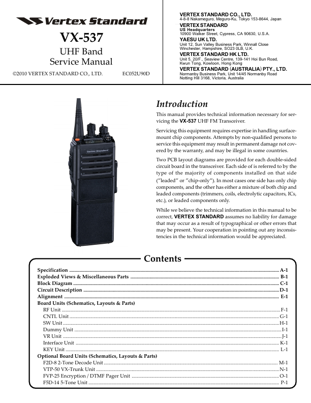
This manual provides technical information necessary for servicing the VX-537 UHF FM Transceiver. Servicing this equipment requires expertise in handling surfacemount chip components.
Published: |