Vanlong Technology SF914C
914.50 MHz SAW Filter
| Part No. | SF914C |
|---|---|
| Datasheet | SF914C Download |
| Manufacturer |  Vanlong Technology |
| Description | 914.50 MHz SAW Filter |
| Buy | Stock & Price |
APPLICATIONS
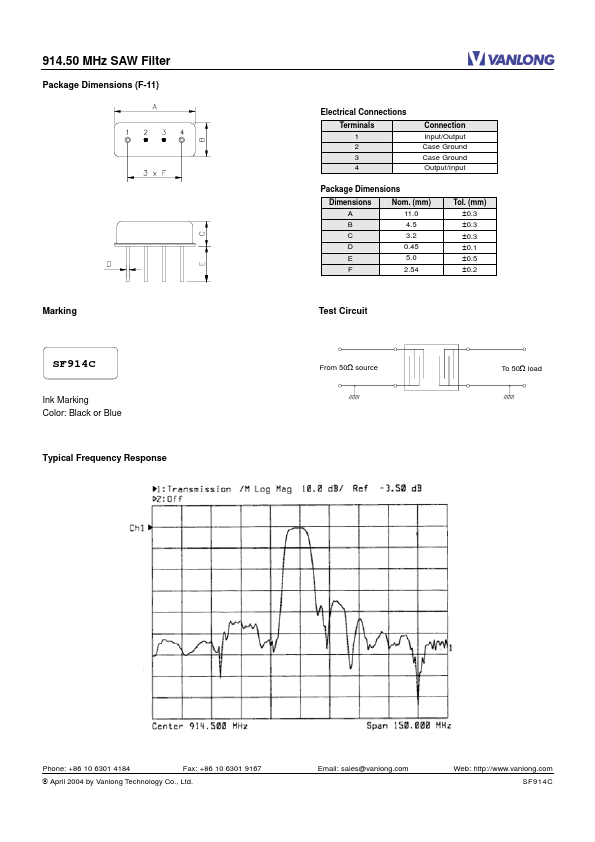
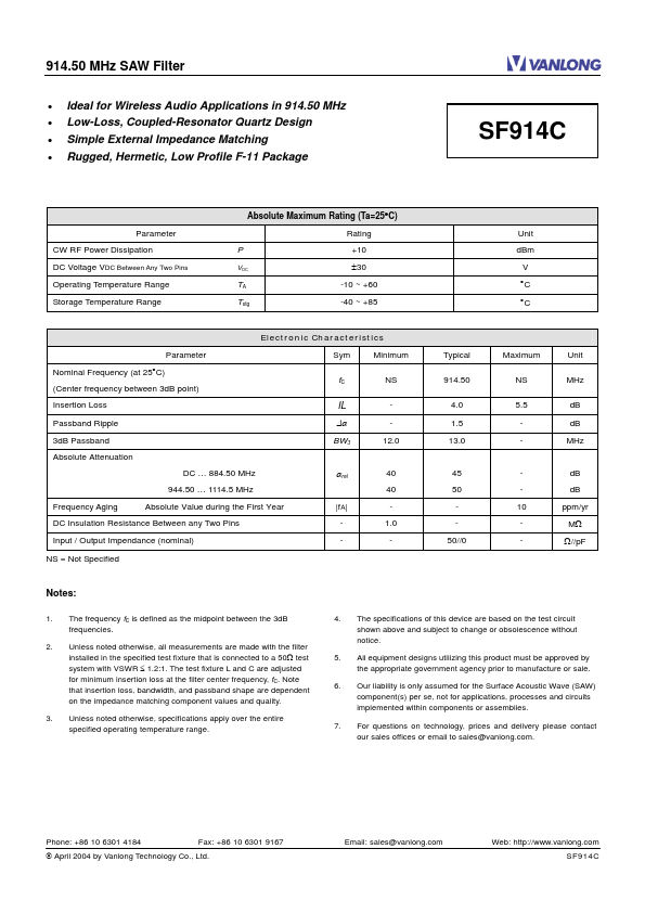
in 914.50 MHz Low-Loss, Coupled-Resonator Quartz Design Simple External Impedance Matching Rugged, Hermetic, Low Profile F-11 Package SF914C Absolute Maximum Rating (Ta=25°C) Parameter CW RF Power Dissipation DC Voltage VDC Between Any Two Pins Operating Temperature Range Storage Temperature Range P VDC Rating +10 ±30 -10 ~ +60 -40 ~ +85 Unit dBm V °C °C TA Tstg Electronic Characteristics Parameter Nominal Frequency (at 25°C) (Center frequency between 3dB point) Insertion Loss Passband Ripple 3dB Passband Absolute Attenuation DC … 884.50 MHz 944.50 … 1114.5 MHz Frequency Aging Absolute Value during the First Year |fA| Sym fC Minimum NS 12.0 Typical 914.50 4.0 1.5 13.0 Maximum NS 5.5 Unit MHz dB dB MHz IL ∆α BW3 αrel 40 40 1.0 - 45 50 50//0 10 - dB dB ppm/yr MΩ Ω//pF DC Insulation Resistance Between any Two Pins Input / Output Impendance (nominal) NS = Not Specified Notes: 1. The frequency fC is defined as the midpoint between the 3dB frequencies. Unless noted otherwise, all measurements are made with the filter installed in the specified test fixture that is connected to a 50Ω test system with VSWR ≤ 1.2:1.