SMA5J30A
SMA5J30A is High Power Density Surface Mount manufactured by Vishay.
- Part of the SMA5J30 comparator family.
- Part of the SMA5J30 comparator family.
Features
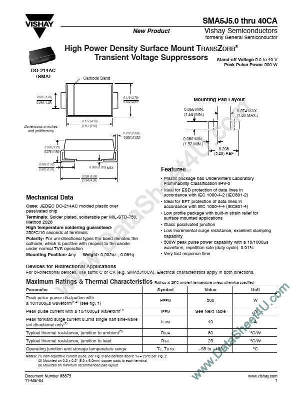
Mechanical Data
Case: JEDEC DO-214AC molded plastic over passivated chip Terminals: Solder plated, solderable per MIL-STD-750, Method 2026 High temperature soldering guaranteed: 250°C/10 seconds at terminals Polarity: For uni-directional types the band denotes the cathode, which is positive with respect to the anode under normal TVS operation Mounting Position: Any Weight: 0.002oz., 0.064g
Devices for Bidirectional Applications
For bi-directional devices, use suffix C or CA (e.g. SMA5J10CA). Electrical characteristics apply in both directions.
Maximum Ratings & Thermal Characteristics Ratings at 25°C ambient temperature unless otherwise specified.
Parameter Peak pulse power dissipation with a 10/1000µs waveform(1,2) (see fig. 1) Peak pulse current with a 10/1000µs waveform(1) Peak forward surge current 8.3ms single half sine-wave uni-directional only(2) Typical thermal resistance, junction to ambient(3) Typical thermal resistance, junction to lead Operating junction and storage temperature range w w
.D w t a
S a e h
- Plastic package has Underwriters Laboratory Flammability Classification 94V-0
- Ideal for ESD protection of data lines in accordance with IEC 1000-4-2 (IEC801-2)
- Ideal for EFT protection of data lines in accordance with IEC 1000-4-4 (IEC801-4)
- Low profile package with built-in strain relief for surface mounted applications
- Glass passivated junction
- Low incremental surge resistance, excellent clamping capability
- 500W peak pulse power capability with a 10/1000µs waveform, repetition rate (duty cycle): 0.01%
- Very fast response time t e
U 4
0.208 (5.28) REF
.c m o
0.074 MAX. (1.88 MAX.)
Symbol PPPM IPPM IFSM RθJA RθJL TJ, TSTG
Value 500 See Next Table 40 80 25
- 55 to +150
Unit W A
Notes: (1) Non-repetitive current pulse, per Fig. 3 and derated above TA = 25°C per Fig. 2 (2) Mounted on 0.2 x 0.2” (5.0 x 5.0mm) copper pads to each terminal (3) Mounted on minimum remended pad layout
Document Number 88875...