M3035S
M3035S is Schottky Barrier Rectifier manufactured by Vishay.
- Part of the M3045S comparator family.
- Part of the M3045S comparator family.
.Data Sheet.co.kr
New Product
M3035S, M3045S
Vishay General Semiconductor
Schottky Barrier Rectifier
Features
- Guardring for overvoltage protection
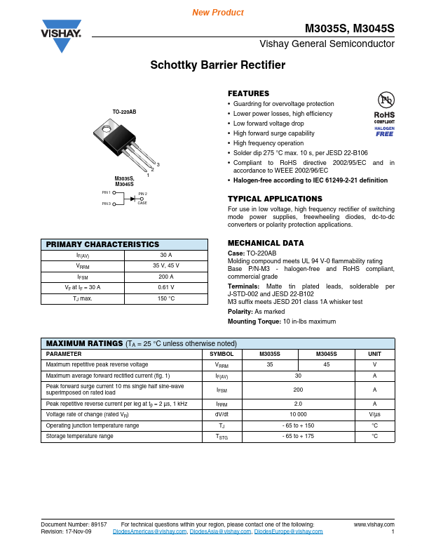
TO-220AB
- Lower power losses, high efficiency
- Low forward voltage drop
- High forward surge capability
- High frequency operation
- Solder dip 275 °C max. 10 s, per JESD 22-B106
2 3
M3035S, M3045S
PIN 1
- pliant to Ro HS directive 2002/95/EC accordance to WEEE 2002/96/EC and in
- Halogen-free according to IEC 61249-2-21 definition
PIN 2 CASE
TYPICAL APPLICATIONS
For use in low voltage, high frequency rectifier of switching mode power supplies, freewheeling diodes, dc-to-dc converters or polarity protection applications.
PIN 3
PRIMARY CHARACTERISTICS
IF(AV) VRRM IFSM VF at IF = 30 A TJ max. 30 A 35 V, 45 V 200 A 0.61 V 150 °C
MECHANICAL DATA
Case: TO-220AB Molding pound meets UL 94 V-0 flammability rating Base P/N-M3
- halogen-free and Ro HS pliant, mercial grade Terminals: Matte tin plated leads, solderable J-STD-002 and JESD 22-B102 M3 suffix meets JESD 201 class 1A whisker test Polarity: As marked Mounting Torque: 10 in-lbs maximum per
MAXIMUM RATINGS (TA = 25 °C unless otherwise noted)
PARAMETER Maximum repetitive peak reverse voltage Maximum average forward rectified current (fig. 1) Peak forward surge current 10 ms single half sine-wave superimposed on rated load Peak repetitive reverse current per leg at tp = 2 µs, 1 k Hz Voltage rate of change (rated VR) Operating junction temperature range Storage temperature range SYMBOL VRRM IF(AV) IFSM IRRM d V/dt TJ TSTG M3035S 35 30 200 2.0 10 000
- 65 to +...