SI5468DC Overview
Key Specifications
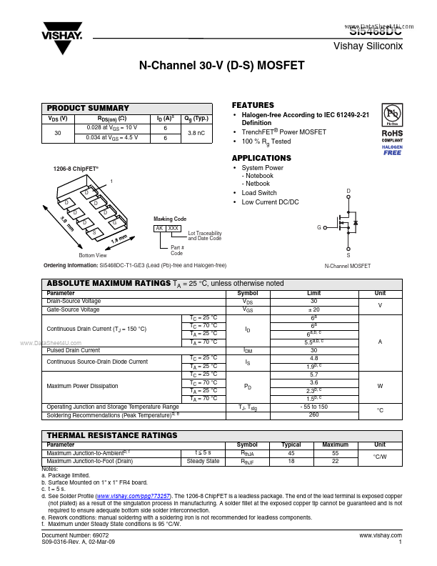
Package: SMD/SMT
Mount Type: Surface Mount
Pins: 8
Height: 1.1 mm
Key Features
- Halogen-free According to IEC 61249-2-21 Definition
- TrenchFET® Power MOSFET
- 100 % Rg Tested
Package: SMD/SMT
Mount Type: Surface Mount
Pins: 8
Height: 1.1 mm
| Seller | Inventory | Price Breaks | Buy |
|---|---|---|---|
| Newark | 4380 | 1+ : 1.06 USD 10+ : 0.735 USD 25+ : 0.669 USD 50+ : 0.529 USD |
View Offer |
| Newark | 0 | 3000+ : 0.21 USD 5000+ : 0.201 USD 10000+ : 0.181 USD 20000+ : 0.166 USD |
View Offer |
| Part Number | Manufacturer | Description |
|---|---|---|
| Si546 | Skyworks Solutions | Crystal Oscillator |