SMR3D
SMR3D is Bulk Metal Foil Technology Precision Molded Surface Mount Resistor manufactured by Vishay.
FEATURES
- Performance Similar to Time Tested S102 Through Hole Resistor
- Temperature Coefficient of Resistance
- Nominal TCR: + 0.6ppm/°C (0°C to + 25°C);
- 0.6ppm/°C (+ 25°C to + 60°C) + 2.2ppm/°C (- 55°C to + 25°C)
- 1.8ppm/°C (+ 25°C to + 125°C)
- Value Range: 5Ω to 80KΩ
- Tight Tolerances: available to ± 0.01 percent
- Power: 0.6 watts @ + 70°C
- Excellent Long Term Stability: ± 0.015%
- Low Thermal EMF: 0.1µV/°C maximum
- Low Noise, High Frequency Operation
- Matched Sets Available
- Terminal Finishes Available: Lead (Pb)-free (Sn 100%) Tin/Lead Alloy (Sn 60% Pb 40%)
Product may not be to scale
The SMR3D is a truly precision molded surface mountable resistor offering all the elements of precision; including lowest TCR, tight tolerances, long term stability, low noise, low thermal EMF, and non-measurable voltage coefficient. It utilizes the Bulk Metal® Foil technology for the resistive element with its inherent and legendary low predictable TCR- and long term stability. This surface mountable product affords similar performance to the time tested S102 molded through-hole product. Voltage division with tight tracking < 3ppm can be achieved with 2 randomly selected units even with a large ratio between the 2 values. The molded SMR3D, while slightly larger and heavier than the Bulk Metal® Foil VSM surface mountable chip resistor, has a rugged construction capable of withstanding significant thermal cycling and allows for board installation without concern for tolerance shifts due to manufacturing processes or mechanical stresses.
- Reference Reason 1 in “7 Technical Reasons to specify BULK METAL® FOIL Resistors.”
TABLE 1
- TOLERANCE VERSUS RESISTANCE VALUE
VALUE (Ω) 100Ω to 80kΩ 20Ω to < 100Ω 10Ω to 20Ω 5Ω to 10Ω STANDARD TOLERANCE (%) ± 0.01 ± 0.02 ± 0.05 ± 0.10
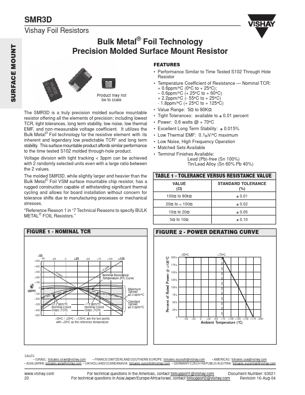
FIGURE 1
- NOMINAL TCR
FIGURE 2
- POWER DERATING CURVE
- 50 +500 +400 +300 +200 +100
- 25
+25
+50
+75
+100
+125
Percent of Rated Power @ +125°C
- 55
200% 175% 150% 125% 100% 75% 50% 25%...