TSOP1136KS1
TSOP1136KS1 is Photo Modules for PCM Remote Control Systems manufactured by Vishay.
- Part of the TSO comparator family.
- Part of the TSO comparator family.
Description
The TSOP11..KS1
- series are miniaturized receivers for infrared remote control systems. PIN diode and preamplifier are assembled on lead frame, the epoxy package is designed as IR filter. The demodulated output signal can directly be decoded by a microprocessor. The main benefit is the operation with short burst transmission codes (e.g. RECS 80) and high data rates.
Features
D Photo detector and preamplifier in one package D Internal filter for PCM frequency D Improved shielding against electrical field disturbance
D Low power consumption D High immunity against ambient light D Enhanced data rate of 3500 bit/s D Operation with short bursts possible
(≥6 cycles/burst)
D TTL and CMOS patibility D Output active low
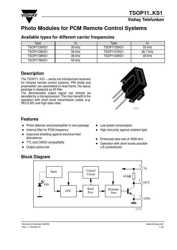
Block Diagram
2 Input Control Circuit 80 k W 3 PIN AGC Band Pass Demodulator 1 GND OUT VS
94 8136
Document Number 82009 Rev. 7, 29 Mar-01
.vishay. 1 (8)
TSOP11..KS1
Vishay Telefunken Absolute Maximum Ratings
Tamb = 25_C Parameter Supply Voltage Supply Current Output Voltage Output Current Junction Temperature Storage Temperature Range Operating Temperature Range Power Consumption Soldering Temperature Test Conditions (Pin 2) (Pin 2) (Pin 3) (Pin 3) Symbol VS IS VO IO Tj Tstg Tamb Ptot Tsd Value
- 0 6.0 5
- 0 6.0 5 100
- 25...+85
- 25...+85 50 260 Unit V m A V m A °C °C °C m W °C
(Tamb 85 °C) t 5s x x
Basic Characteristics
Tamb = 25_C Parameter Supply Current (Pin 2) Supply Voltage (Pin 2) Transmission Distance Output Voltage Low (Pin 3) Irradiance (30
- 40 k Hz) Irradiance (56 k Hz) Irradiance Directivity Ev = 0, test signal see fig.8, IR diode TSAL6200, IF = 0.4 A IOSL = 0.5 m A,Ee = 0.7 m W/m2, f = fo, test signal see fig.7 Test signal see fig.7 Test signal see fig.8 Test signal see fig.7 Test signal see fig.8 Test signal see fig.7 Angle of half transmission distance Test Conditions VS = 5 V, Ev = 0 VS = 5 V, Ev = 40 klx, sunlight Symbol ISD ISH VS d VOSL Ee min Ee min Ee min Ee min Ee max ϕ1/2 0.4 0.35 0.45 0.40 30 ±45 Min 0.4...