TSOP1240TB1
TSOP1240TB1 is Photo Modules for PCM Remote Control Systems manufactured by Vishay.
Description
The TSOP12..TB1
- series are miniaturized receivers for infrared remote control systems. PIN diode and preamplifier are assembled on lead frame, the epoxy package is designed as IR filter. The demodulated output signal can directly be decoded by a microprocessor. The main benefit is the reliable function even in disturbed ambient and the protection against uncontrolled output pulses.
GND VS OUT
94 8692
Features
D Photo detector and preamplifier in one package D Internal filter for PCM frequency D Improved shielding against electrical field disturbance
Special Features
D Enhanced immunity against all kinds of disturbance light
D No occurrence of disturbance pulses at the output
TTL and CMOS patibility Output active low Low power consumption Suitable burst length ≥10 cycles/burst
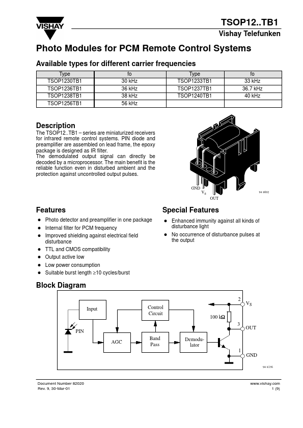
Block Diagram
2 Input Control Circuit 100 k W 3 PIN AGC Band Pass Demodulator 1 GND
94 8136
Document Number 82020 Rev. 9, 30-Mar-01
.vishay. 1 (9)
TSOP12..TB1
Vishay Telefunken Absolute Maximum Ratings
Tamb = 25_C Parameter Supply Voltage Supply Current Output Voltage Output Current Junction Temperature Storage Temperature Range Operating Temperature Range Power Consumption Soldering Temperature Test Conditions (Pin 2) (Pin 2) (Pin 3) (Pin 3) Symbol VS IS VO IO Tj Tstg Tamb Ptot Tsd Value
- 0 6.0 5
- 0 6.0 5 100
- 25...+85
- 25...+85 50 260 Unit V m A V m A °C °C °C m W °C
(Tamb 85 °C) t 5s x x
Basic Characteristics
Tamb = 25_C Parameter Supply (Pin 2) y Current ( ) Supply Voltage (Pin 2) Transmission Distance Output Voltage Low (Pin 3) Irradiance (30
- 40 k Hz) Test Conditions VS = 5 V, Ev = 0 VS = 5 V, Ev = 40 klx, sunlight Ev = 0, test signal see fig.7, IR diode TSAL6200, IF = 400 m A IOSL = 0.5 m A,Ee = 0.7 m W/m2, f = fo, tp/T = 0.4 Pulse width tolerance: tpi
- 5/fo < tpo < tpi + 6/fo, test signal see fig.7 Pulse width tolerance: tpi
- 5/fo < tpo < tpi + 6/fo, test signal see fig.7 tpi
- 5/fo < tpo < tpi + 6/fo Angle of half transmission distance...