Vishay 150KS40
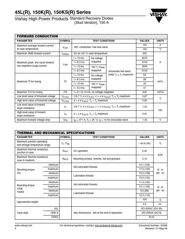
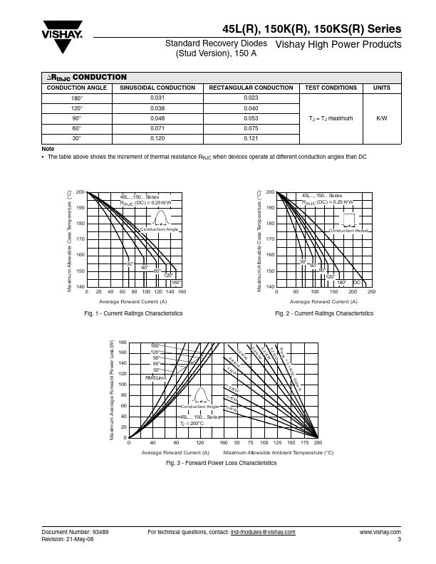
The table above shows the increment of thermal resistance RthJC when devices operate at different conduction angles than DC Maximum Allowable Case T emperature (°C) Maximum Allowable Case T emperature (°C) 200 190 180 Conduction Angle 200 190 180 45L...,150...| Part No. | 150KS40 |
|---|---|
| Datasheet | 150KS40 Download |
| Manufacturer |  Vishay |
| Description | Standard Recovery Diodes |
| Buy | Stock & Price |
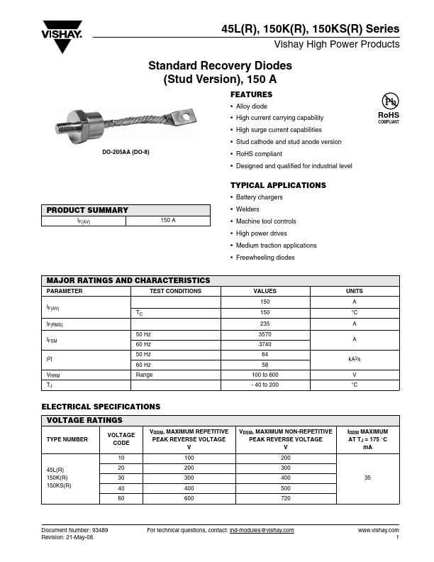
FEATURES
● Alloy diode● High current carrying capability
● High surge current capabilities
● Stud cathode and stud anode version DO-205AA (DO-8) RoHS COMPLIANT
● RoHS compliant
● Designed and qualified for industrial level
TYPICAL APPLICATIONS
● Battery chargers PRODUCT SUMMARY IF(AV) 150 A● Welders
● Machine tool controls
● High power drives
● Medium traction applications
● Freewheeling diodes MAJOR RATINGS AND CHARACTERISTICS PARAMETER IF(AV) IF(RMS) IFSM I2 t VRRM TJ 50 Hz 60 Hz 50 Hz 60 Hz Range TEST CONDITIONS VALUES 150 UNITS A °C A A TC 150 235 3570 3740 64 58 100 to 600 - 40 to 200 kA2s V °C
ELECTRICAL SPECIFICATIONS
VOLTAGE RATINGS TYPE NUMBER VOLTAGE CODE 10 45L(R) 150K(R) 150KS(R) 20 30 40 60 VRRM, MAXIMUM REPETITIVE PEAK REVERSE VOLTAGE V 100 200 300 400 600 VRSM, MAXIMUM NON-REPETITIVE PEAK REVERSE VOLTAGE V 200 300 400 500 720 35 IRRM MAXIMUM AT TJ = 175 °C mA Document Number: 93489 Revision: 21-May-08 For technical questions, contact: ind-modules@vishay.com 1 Datasheet...