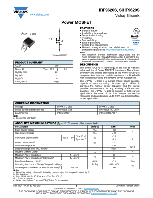
IRF9620S
IRF9620S is Power MOSFET manufactured by Vishay.
FEATURES
- Surface-mount
- Available in tape and reel
- Dynamic d V/dt rating
- P-channel
Available
- Fast switching
- Ease of paralleling
- Simple drive requirements
Available
- Material categorization: for definitions of pliance please see .vishay./doc?99912
Note
- This datasheet provides information about parts that are
Ro HS-pliant and / or parts that are non Ro HS-pliant. For example, parts with lead (Pb) terminations are not Ro HS-pliant. Please see the information / tables in this datasheet for details
DESCRIPTION
The power MOSFETs technology is the key to Vishay’s advanced line of Power MOSFET transistors. The efficient geometry and unique processing of the Power MOSFETs design achieve very low on-state resistance bined with high transconductance and extreme device ruggedness.
The D2PAK (TO-263) is a surface-mount power package capable of acmodating die sizes up to HEX-4. It provides the highest power capability and the lowest possible on-resistance in any existing surface-mount package. The D2PAK (TO-263) is suitable for high current applications because of its low internal connection resistance and can dissipate up to 2.0 W in a typical surface mount application.
D2PAK (TO-263) Si HF9620STRL-GE3 a IRF9620STRLPb F a
ABSOLUTE MAXIMUM RATINGS (TC = 25 °C, unless otherwise noted)
PARAMETER
SYMBOL
Drain-Source Voltage Gate-Source Voltage
Continuous Drain Current
Pulsed Drain Current a Linear Derating Factor
VGS at -10 V
TC = 25 °C TC = 100 °C
Linear Derating Factor (PCB mount) e
Inductive Current, Clamp Maximum Power Dissipation Maximum Power Dissipation (PCB mount) e Peak Diode Recovery d V/dt c
TC = 25 °C TA = 25 °C
ILM PD d V/dt
Operating Junction and Storage Temperature Range Soldering Remendations (Peak temperature) d
For 10 s
TJ, Tstg
Notes a. Repetitive rating; pulse width limited by maximum junction temperature (see fig. 5) b. Not Applicabl c. ISD ≤ -3.5 A, d I/dt ≤ 95 A/μs, VDD ≤ VDS, TJ ≤ 150 °C d. 1.6 mm from...