FEATURES
D Continuous Voltage-Controlled Resistance D High Off-Isolation D High Input Impedance BENEFITS D Gain Ranging Capability/Wide Range Signal Attenuation D No Circuit Interaction D Simplified Drive APPLICATIONS
D Variable Gain Amplifiers D Voltage Controlled Oscillator D AGC DESCRIPTION
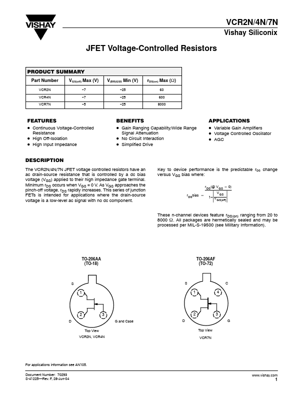
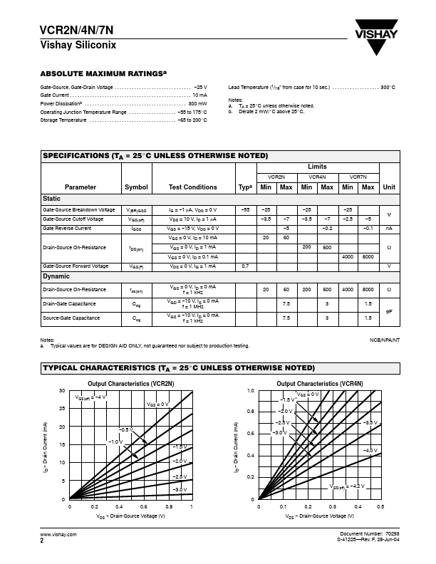
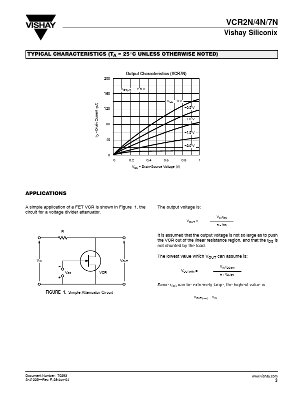
Minimum rDS occurs when VGS = 0 V. As VGS approaches the pinch-off voltage, rDS rapidly increases. Key to device performance is the predictable rDS change versus VGS bias where: r DS(@ V GS + 0) r DSbias [ V GS 1– V GS(off) Ť Ť These n-channel devices feature rDS(on) ranging from 20 to 8000 W . All packages are hermetically sealed and may be processed per MIL-S-19500 (see Military Information). TO-206AA (TO-18) TO-206AF (TO-72) S S C 1 1 4 2 D Top View 3 G and Case D 2 3 G Top View VCR7N VCR2N, VCR4N For applications information see AN105. Document Number: 70293 S-41225—Rev. F, 28-Jun-04 1 VCR2N/4N/7N Vishay Siliconix ABSOLUTE MAXIMUM RATINGSa Gate-Source, Gate-Drain Voltage . . . . . . . . . . . Vishay