WICI MM4001
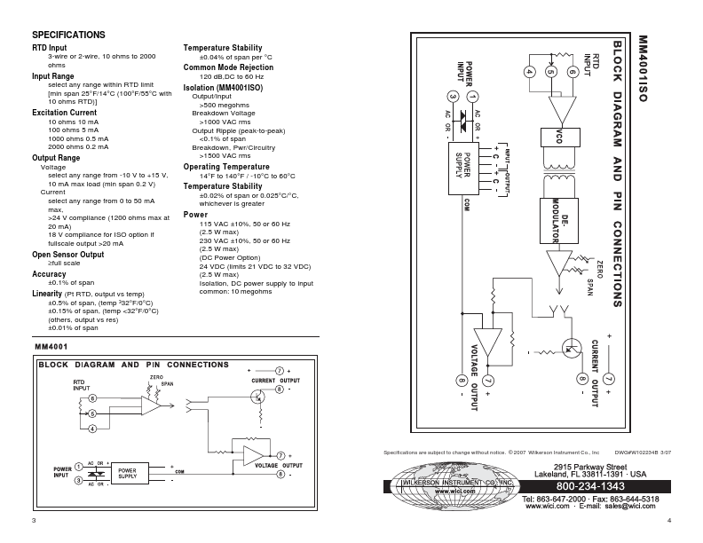
The MM4001 modules are shipped precalibrated, if there is a need to recalibrate, proceed as follows: Refer to the instrument's label to determine your instrument's supply voltage and input and output ranges. DESCRIPTION The MM4001 modules are used to provide an output voltage or current proportional to an RTD input signal.| Part No. | MM4001 |
|---|---|
| Datasheet | MM4001 Download |
| Manufacturer |  WICI |
| Description | RTD INPUT TRANSMITTERS |
| Buy | Stock & Price |
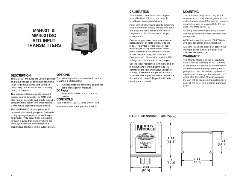
CALIBRATION Refer to the "Block Diagram and Pin Connections" for pin connections. Connect a precision decade resistance, potentiometer or RTD simulator to the input. To avoid errors due to the resistances of the connection wires, use a three-wire connection as shown in the “Block Diagram and Pin Connections”. Connect a precision DC voltage or current meter to the output. Set the input resistance to the low end of the input range and adjust the ZERO control for the low-end output voltage or current. Increase the input resistance to full scale and adjust the SPAN control for the full-scale output. Repeat until both readings are correct. MOUNTING The module is designed to plug into a standard 8 pin relay socket. (MP008) is a molded plastic socket that can be mounted on a flat surface or snapped into 2¾ inch wide PVC track (TRK 48). A spring hold-down clip (CLP1) is available for installations where vibration may be a problem. A DIN-rail mounted socket (DMP008) is available for 35mm symmetrical rail.