• Part: 54ACT251
  • Description: 8-Input Multiplexer
  • Manufacturer: Texas Instruments
  • Size: 138.06 KB
Download 54ACT251 Datasheet PDF
Texas Instruments
54ACT251
54ACT251 is 8-Input Multiplexer manufactured by Texas Instruments.
- Part of the 54AC251 comparator family.
FEATURES - 23 ICC Reduced by 50% - Multifunctional Capability - On-Chip Select Logic Decoding - Inverting and Noninverting TRI-STATE Outputs - Outputs Source/Sink 24 m A - 'ACT251 has TTL-patible Inputs - Standard Military Drawing (SMD) - 'AC251: 5962-87692 - 'ACT251: 5962-89599 DESCRIPTION 
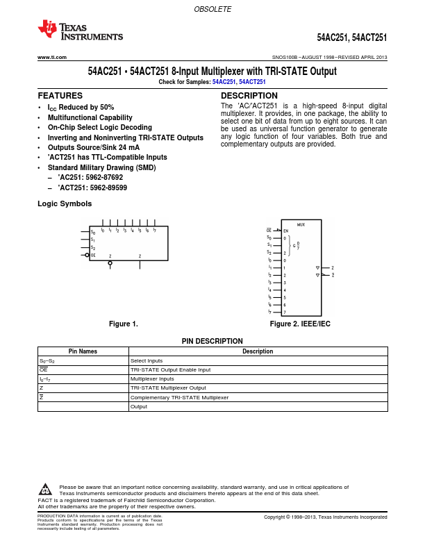
The 'AC/'ACT251 is a high-speed 8-input digital multiplexer. It provides, in one package, the ability to select one bit of data from up to eight sources. It can be used as universal function generator to generate any logic function of four variables. Both true and plementary outputs are provided. Logic Symbols S0- S2 OE I0- I7 Z Z Figure 1. Figure 2. IEEE/IEC Pin Names PIN DESCRIPTION Description Select Inputs TRI-STATE Output Enable Input Multiplexer Inputs TRI-STATE Multiplexer Output plementary TRI-STATE Multiplexer Output Please be aware that an important notice concerning availability, standard warranty, and use in critical applications of Texas Instruments semiconductor products and disclaimers thereto appears at the end of this data sheet. FACT is a registered trademark of Fairchild Semiconductor Corporation. All other trademarks are the property of their respective owners. PRODUCTION DATA information is current as of publication date. Products conform to specifications per the terms of the Texas Instruments standard warranty. Production processing does not necessarily include testing of all parameters. Copyright © 1998- 2013, Texas Instruments Incorporated 54AC251, 54ACT251 SNOS100B - AUGUST 1998 - REVISED APRIL 2013 Connection Diagram OBSOLETE .ti. Figure 3. 16-Pin CERDIP or CLGA See NAD0016A Package Figure 4. 20-Pin LCCC See NAJ0020A Package FUNCTIONAL DESCRIPTION This device is a logical implementation of a single-pole, 8-position switch with the switch position controlled by the state of three Select inputs, S0, S1, S2. Both true and plementary outputs are provided. The Output Enable input ( OE) is active LOW. When it is activated, the logic...