APPLICATIONS
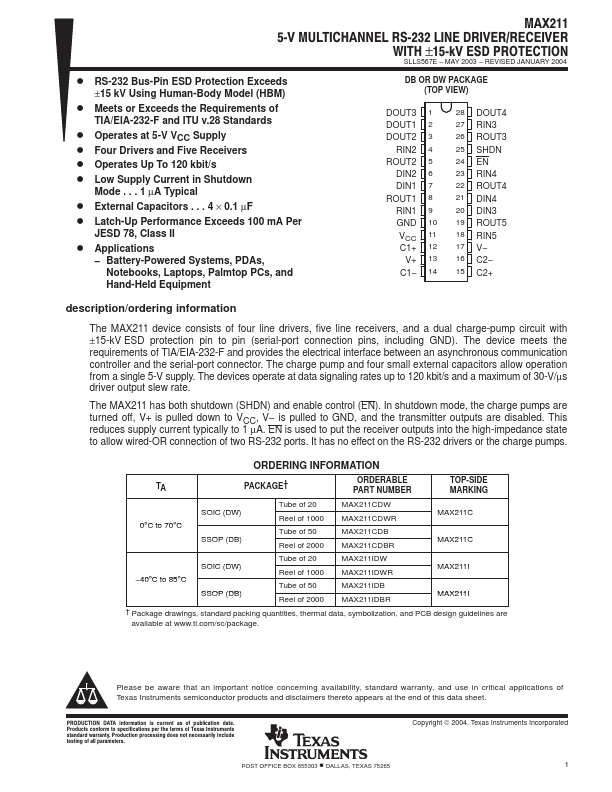
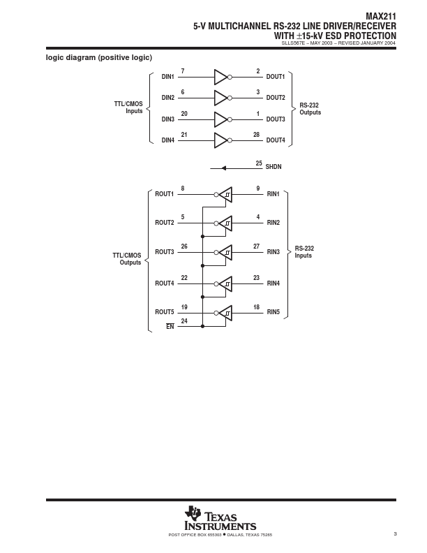
− Battery-Powered Systems, PDAs, Notebooks, Laptops, Palmtop PCs, and Hand-Held Equipment DB OR DW PACKAGE (TOP VIEW) DOUT3 1 DOUT1 2 DOUT2 3 RIN2 4 ROUT2 5 DIN2 6 DIN1 7 ROUT1 8 RIN1 9 GND 10 VCC 11 C1+ 12 V+ 13 C1− 14 28 DOUT4 27 RIN3 26 ROUT3 25 SHDN 24 EN 23 RIN4 22 ROUT4 21 DIN4 20 DIN3 19 ROUT5 18 RIN5 17 V− 16 C2− 15 C2+ description/ordering information The devices operate at data signaling rates up to 120 kbit/s and a maximum of 30-V/µs driver output slew rate. The MAX211 has both shutdown (SHDN) and enable control (EN). In shutdown mode, the charge pumps are turned off, V+ is pulled down to VCC, V− is pulled to GND, and the transmitter outputs are disabled. This reduces supply current typically to 1 µA. EN is used to put the receiver outputs into the high-impedance state to allow wired-OR connection of two RS-232 ports. It has no effect on the RS-232 drivers or the charge pumps. ORDERING INFORMATION TA PACKAGE† ORDERABLE PART NUMBER TOP-SIDE MARKING 0°C to 70°C SO... Texas Instruments