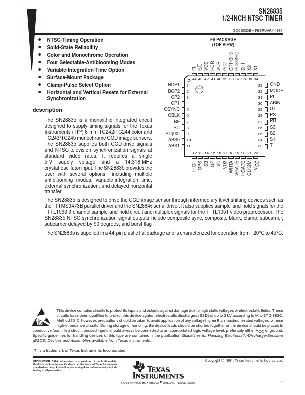
DESCRIPTION
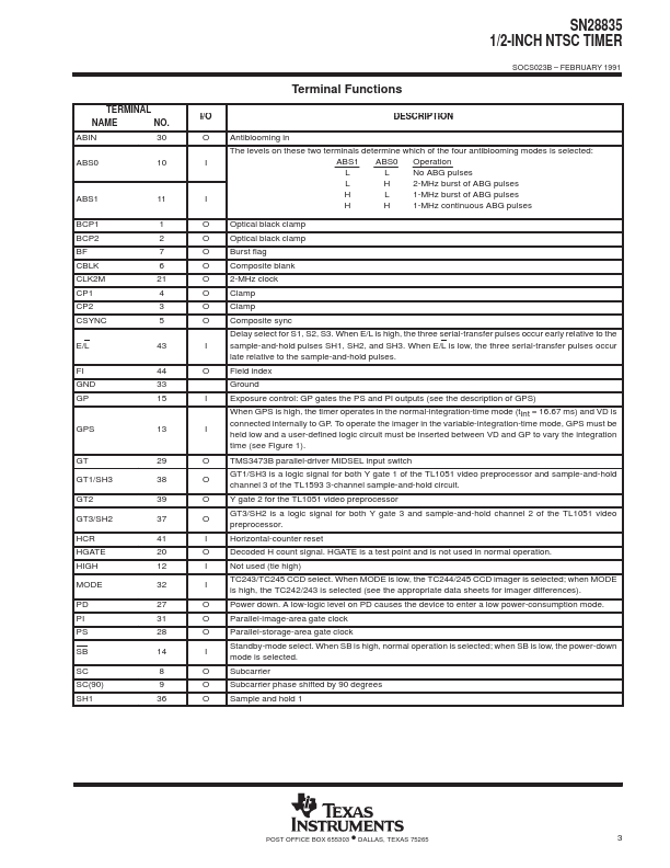
O Antiblooming in The levels on these two terminals determine which of the four antiblooming modes is selected: I ABS1 ABS0 Operation L L No ABG pulses L H 2-MHz burst of ABG pulses I H L 1-MHz burst of ABG pulses H H 1-MHz continuous ABG pulses O Optical black clamp O Optical black clamp O Burst flag O Composite blank O 2-MHz clock O Clamp O Clamp O Composite sync Delay select for S1, S2, S3. When E/L is high, the three serial-transfer pulses occur early relative to the I sample-and-hold pulses SH1, SH2, and SH3. When E/L is low, the three serial-transfer pulses occur late relative to the sample-and-hold pulses. O Field index Ground I Exposure control: GP gates the PS and PI outputs (see the description of GPS) When GPS i Texas Instruments