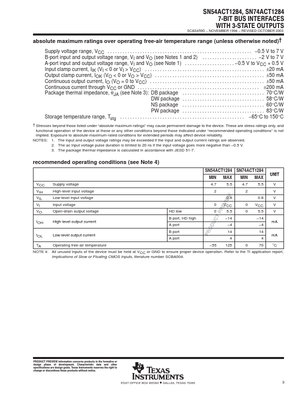
ELECTRICAL SPECIFICATIONS
description/ordering information SN54ACT1284 . . . J OR W PACKAGE SN74ACT1284 . . . DB, DW, NS, OR PW PACKAGE (TOP VIEW) A1 1 A2 2 A3 3 A4 4 GND 5 GND 6 A5 7 A6 8 A7 9 DIR 10 20 B1 19 B2 18 B3 17 B4 16 VCC 15 VCC 14 B5 13 B6 12 B7 11 HD SN54ACT1284 . . . FK PACKAGE (TOP VIEW) B2 B1 A1 A2 A3 The devices allow data transmission in either the A-to-B or the B-to-A direction for bits 1, 2, 3, and 4, depending on the logic level at the direction-control (DIR) input. Bits 5, 6, and 7, however, always transmit in the A-to-B direction. A7 DIR HD A4 GND GND A5 A6 3 2 1 20 19 4 18 5 17 6 16 7 15 8 14 9 10 11 12 13 B3 B4 VCC VCC B5 B7 B6 The output drive for each mode is determined by the high-drive (HD) control pin. When HD is high, the high drive is delivered by the totem-pole configuration, and when HD is low, the outputs are open drain. This meets the drive requirements as specified in the IEEE 1284-I (level-1 type) and the IEEE 1284-II (level-2 type) parallel peripheral-interface specification. Texas Instruments