SN74LV8151 Overview
Key Specifications
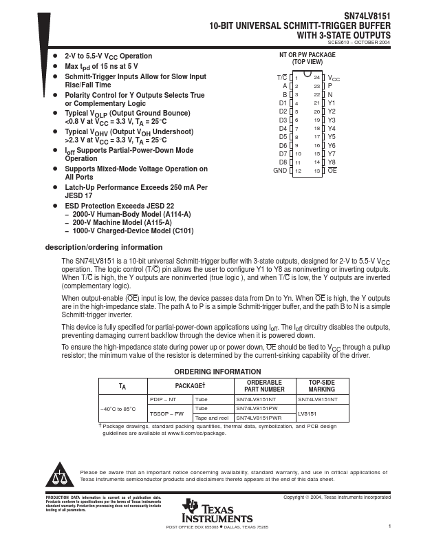
Package: TFSOP
Mount Type: Surface Mount
Pins: 24
Max Voltage (typical range): 5.5 V
Key Features
- 2000-V Human-Body Model (A114-A)
- 200-V Machine Model (A115-A)
| Part | SN74LV8151 |
|---|---|
| Description | 10-BIT UNIVERSAL SCHMITT-TRIGGER BUFFER |
| Manufacturer | Texas Instruments |
| Size | 481.44 KB |
Package: TFSOP
Mount Type: Surface Mount
Pins: 24
Max Voltage (typical range): 5.5 V
| Seller | Inventory | Price Breaks | Buy |
|---|---|---|---|
| DigiKey | 0 | 2000+ : 0.7102 USD 4000+ : 0.6931 USD 6000+ : 0.68454 USD 10000+ : 0.67505 USD |
View Offer |
| Arrow Electronics | 0 | 2000+ : 0.7292 USD 4000+ : 0.7219 USD 6000+ : 0.7147 USD 8000+ : 0.7075 USD |
View Offer |
| Part Number | Manufacturer | Description |
|---|---|---|
| BUF04 | Analog Devices | Closed-Loop High Speed Buffer |
| 74HC125 | NXP Semiconductors | Quad buffer/line driver |
| BUF03 | Analog Devices | High Speed Voltage Follower/Buffer |