SN74LVC543A Overview
Key Specifications
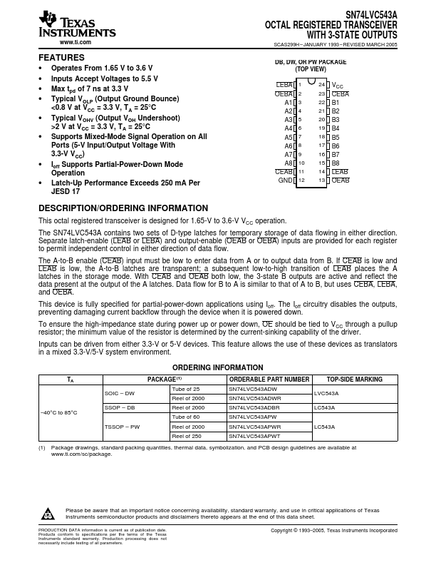
Package: SSOP
Mount Type: Surface Mount
Pins: 24
Max Voltage (typical range): 3.6 V
Key Features
- Operates From 1.65 V to 3.6 V
- Inputs Accept Voltages to 5.5 V
- Max tpd of 7 ns at 3.3 V
- Typical VOLP (Output Ground Bounce) <0.8 V at VCC = 3.3 V, TA = 25°C
- Typical VOHV (Output VOH Undershoot) >2 V at VCC = 3.3 V, TA = 25°C