SN75126
SN75126 is Quadruple Line Driver manufactured by Texas Instruments.
description
The SN75126 quadruple line driver is designed to meet the IBM 360/370 I/O specification A22-6974-3. The output voltage is 3.11 V minimum (at IOH =
- 59.3 m A) over the remended ranges of supply voltage (4.5 V to 5.95 V) and temperature. Driver outputs use a fault-detection current-limit circuit to allow high drive current but still minimize power dissipation when the output is shorted to ground. The SN75126 is patible with standard TTL logic and supply voltages.
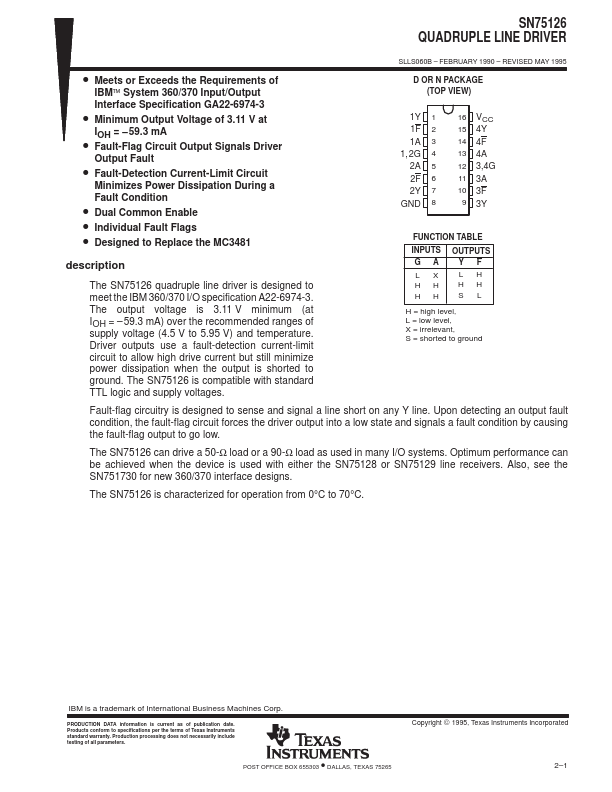
D OR N PACKAGE (TOP VIEW)
1Y 1F 1A 1, 2G 2A 2F 2Y GND
1 2 3 4 5 6 7 8
16 VCC 15 4Y 14 4F 13 4A 12 3,4G 11 3A 10 3F 9 3Y
FUNCTION TABLE
INPUTS
LX HH HH
OUTPUTS YF
LH HH SL
H = high level, L = low level, X = irrelevant, S = shorted to ground
Fault-flag circuitry is designed to sense and signal a line short on any Y line. Upon detecting an output fault condition, the fault-flag circuit forces the driver output into a low state and signals a fault condition by causing the fault-flag output to go low.
The SN75126 can drive a 50-Ω load or a 90-Ω load as used in many I/O systems. Optimum performance can be achieved when the device is used with either the SN75128 or SN75129 line receivers. Also, see the SN751730 for new 360/370 interface designs.
The SN75126 is characterized for operation from 0°C to 70°C.
IBM is a trademark of International Business Machines Corp.
PRODUCTION DATA information is current as of publication date. Products conform to specifications per the terms of Texas Instruments standard warranty. Production processing does not necessarily include testing of all parameters.
- POST OFFICE BOX 655303 DALLAS, TEXAS 75265
Copyright © 1995, Texas Instruments Incorporated 2- 1
SN75126 QUADRUPLE LINE DRIVER
SLLS060B
- FEBRUARY 1990
- REVISED MAY 1995 logic symbol†
1A 3 1, 2G 4
2A 5 11
3A
& 1EN2 G1
2 & 3EN4
G3 4
12 3, 4G
13 4A
2 1F
1 1Y 6
2F
7 2Y 10 3F
9 3Y 14 4F
15 4Y
† This symbol is in accordance with ANSI/IEEE Std 91-1984 and IEC Publication 617-12. logic diagram...