SN75ALS121 Overview
Key Specifications
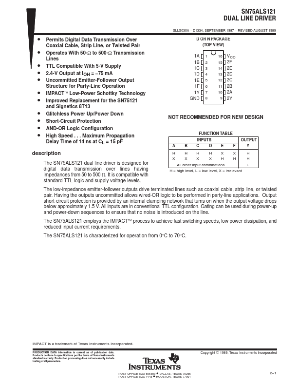
Package: PDIP
Pins: 16
Description
The SN75ALS121 dual line driver is designed for digital data transmission over lines having impedances from 50 to 500 Ω. It is compatible with standard TTL logic and supply voltage levels.