TL1453C
Description
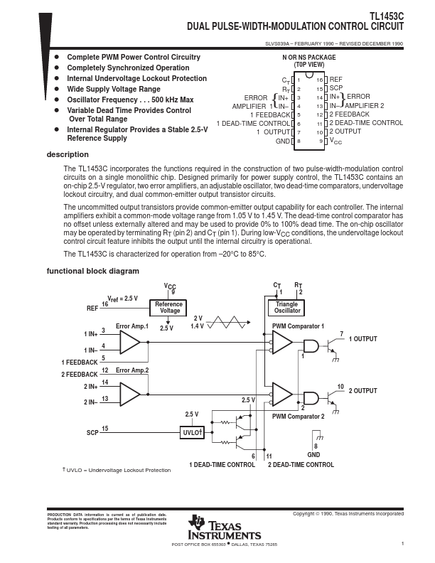
SLVS039A - FEBRUARY 1990 - REVISED DECEMBER 1990 N OR NS PACKAGE (T0P VIEW) CT { RT ERROR IN+ AMPLIFIER 1 IN- 1 FEEDBACK 1 DEAD-TIME CONTROL 1 OUTPUT GND 1 2 3 4 5 6 7 8 16 REF 15 SCP }14 IN+ ERROR 13 IN- AMPLIFIER 2 12 2 FEEDBACK 11 2 DEAD-TIME CONTROL 10 2 OUTPUT 9 VCC The TL1453C incorporates the functions required in the construction of two pulse-width-modulation control circuits on a single monolithic chip. Designed primarily for power supply control, the TL1453C contains an on-chip 2.5-V regulator, two error amplifiers, an adjustable oscillator, two dead-time comparators, undervoltage lockout circuitry, and dual common-emitter output transistor circuits.
Key Features
- 5 V 2V 1.4 V 4 1 IN-