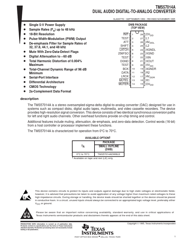
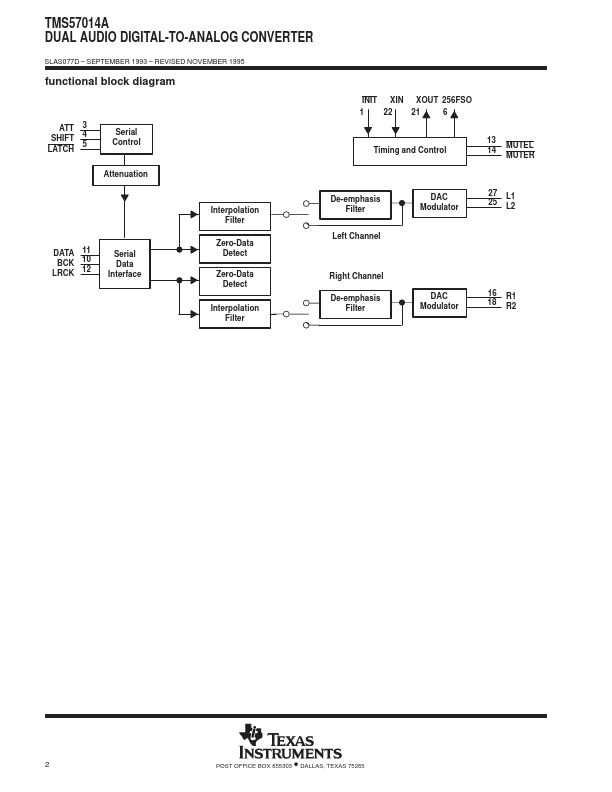
DESCRIPTION
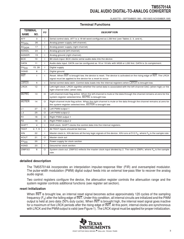
ATT 3 I Serial control data. ATT is a 16-bit word configured as LSB first (see Tables 2, 3, and 4). AVDDL AVDDR AGNDL 26 17 24 I Analog power supply (left channel) I Analog power supply (right channel) I Analog ground (left channel) AGNDR 19 I Analog ground (right channel) BCK 10 I Bit clock input. BCK clocks serial audio data into the device. DATA 11 I Audio data input. DATA can be configured as 16 or 18 bits with MSB or LSB first. DATA is 2s complement. DVDD DGND 15, 28 8 I Digital supply I Digital ground INIT 1 I Reset. When INIT is brought low, the device is reset. The device is activated on the rising edge of INIT. The LRCK signal must be applied to the device for a reset to occur. LATCH 5 I Serial-control data latch. Control data loads into the internal registers when LATCH is brought low. LRCK 12 I Left /right clock. LRCK signifies whether the serial data is associated with the left-channel DAC (when high) or the right-channel DAC (when low). MUTEL 13 O Left-channel mute flag active. Texas Instruments