RM8001 Overview
Key Features
- eclass: 27270590 / 27-27-05-90
- Friedrichstraße 1
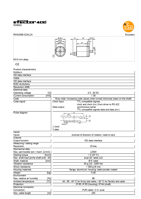
| Part | RM8001 |
|---|---|
| Description | Sensor for Motion Control |
| Manufacturer | ifm |
| Size | 76.84 KB |
| Seller | Inventory | Price Breaks | Buy |
|---|---|---|---|
| TME | 0 | 1+ : 396.33 USD | View Offer |
| TME | 0 | 1+ : 396.33 EUR | View Offer |
| Part Number | Manufacturer | Description |
|---|---|---|
| RM800DG-90F | Mitsubishi Electric | HIGH VOLTAGE DIODE MODULES |