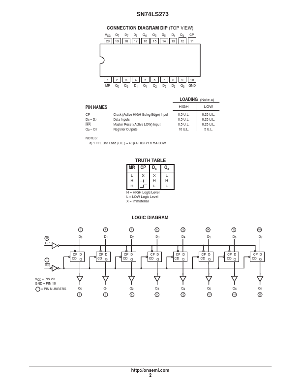
DESCRIPTION
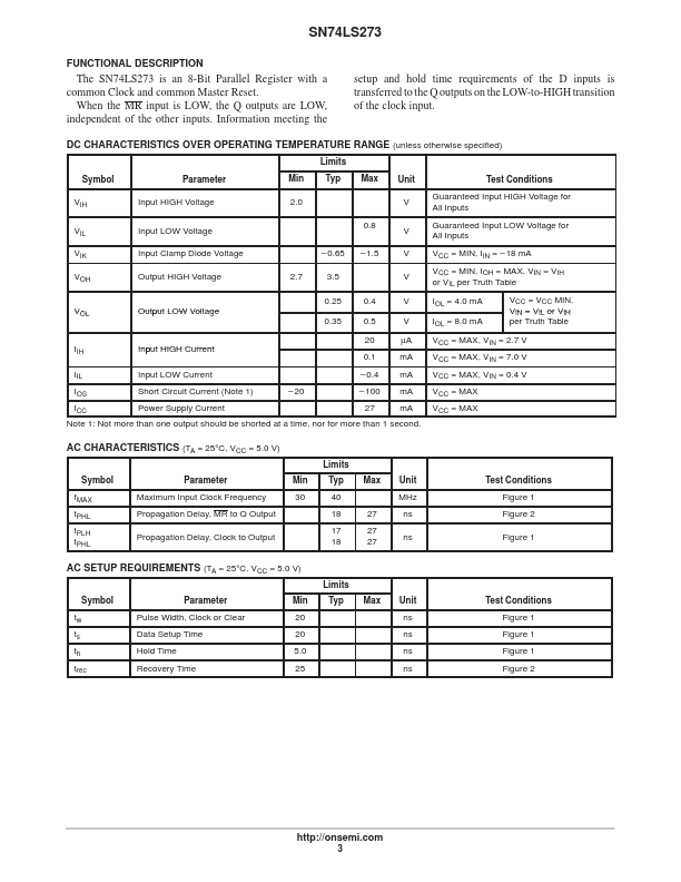
Information meeting the setup and hold time requirements of the D inputs is transferred to the Q outputs on the LOW-to-HIGH transition of the clock input. DC CHARACTERISTICS OVER OPERATING TEMPERATURE RANGE (unless otherwise specified) Limits Symbol VIH VIL VIK VOH Parameter Input HIGH Voltage Input LOW Voltage Input Clamp Diode Voltage Output HIGH Voltage 2.7 – 0.65 3.5 0.25 VOL O Output LOW Voltage 0.35 IIH IIL IOS ICC Input HIGH Current 0.1 Input LOW Current Short Circuit Current (Note 1) Power Supply Current – 20 – 0.4 – 100 27 0.5 20 V µA mA mA mA mA IOL = 8.0 mA 0.4 Min 2.0 0.8 – 1.5 Typ Max Unit V V V V V Test Conditions Guaranteed Input HIGH Voltage for All Inputs Guaranteed Input LOW Voltage for All Inputs VCC = MIN, IIN = – 18 mA VCC = MIN, IOH = MAX, VIN = VIH or VIL per Truth Table IOL = 4.0 mA VCC = VCC MIN, VIN = VIL or VIH per Truth Table VCC = MAX, VIN = 2.7 V VCC = MAX, VIN = 7.0 V VCC = MAX, VIN = 0.4 V VCC = MAX VCC = MAX Note 1: Not more than one output should be shorted at a time, nor for more than 1 second. onsemi