onsemi IRFW630B
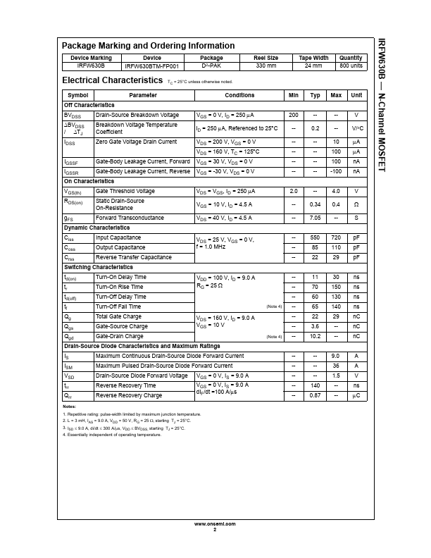
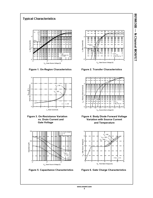
This advanced technology has been especially tailored to minimize on-state resistance, provide superior switching performance, and withstand high energy pulse in the avalanche and commutation mode. These devices are well suited for high efficiency switching DC/DC converters, switch mode power supplies, DC-AC converters for uninterrupted power supply and motor control.| Part No. | IRFW630B |
|---|---|
| Datasheet | IRFW630B Download |
| Manufacturer |  onsemi |
| Description | N-Channel MOSFET |
| Buy | Stock & Price |
FEATURES
DESCRIPTION
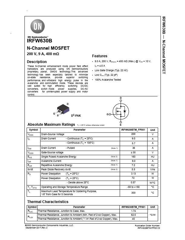
These N-Channel enhancement mode power field effect transistors are produced using ON Semiconductors proprietary, planar, DMOS technology.● 9.0 A, 200 V, RDS(on) = 400 mΩ (Max.) @ VGS = 10 V, ID = 4.5 A
● Low Gate Charge (Typ. 22 nC)
● Low Crss (Typ. 22 pF)
● 100% Avalanche Tested D D G S D2-PAK G
ABSOLUTE MAXIMUM RATINGS
TC = 25°C unless otherwise noted. Symbol Parameter VDSS ID Drain-Source Voltage Drain Current - Continuous (TC = 25°C) - Continuous (TC = 100°C) IDM VGSS EAS IAR EAR dv/dt Drain Current - Pulsed Gate-Source voltage Single Pulsed Avalanche Energy Avalanche Current Repetitive Avalanche Energy Peak Diode Recovery dv/dt PD Power Dissipation (TA = 25°C)* Power Dissipation (TC = 25°C) - Derate above 25°C TJ, TSTG TL Operating and Storage Temperature Range Maximum Lead Temperature for Soldering Purpose, 1/8” from Case for 5 Seconds S (Note 1) (Note 2) (Note 1) (Note 1) (Note 3) IRFW630BTM_FP001 200 9.0 5.7 36 ± 30 160 9.0 7.2 5.5 3.13 72 0.57 -55 to +150 300 Unit V A A A V mJ A mJ V/ns W W W/°C °C °C Thermal Characteristics Symbol Parameter R●JC Thermal Resistance, Junction to Case, Max.