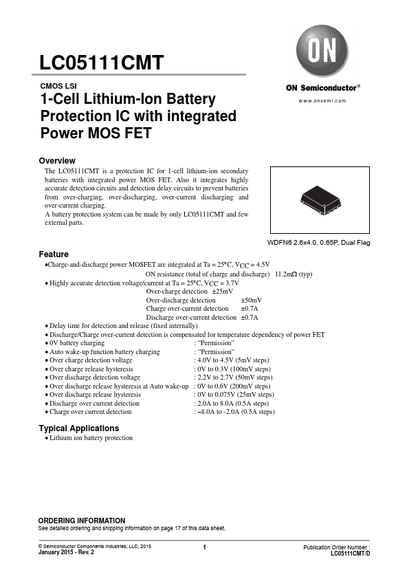
APPLICATIONS
● Lithium ion battery protection ORDERING INFORMATION See detailed ordering and shipping information on page 17 of this data sheet. © Semiconductor Components Industries, LLC, 2015 January 2015 - Rev. 2 1 Publication Order Number : LC05111CMT/D LC05111CMT Specifications ABSOLUTE MAXIMUM RATINGS
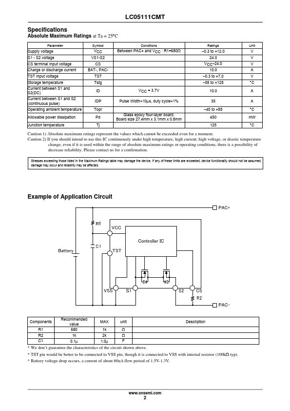
at Ta = 25C Parameter Supply voltage S1 - S2 voltage CS terminal Input voltage Charge or discharge current TST Input voltage Storage temperature Current between S1 and S2(DC) Current between S1 and S2 (continuous pulse) Operating ambient temperature Allowable power dissipation Junction temperature Symbol VCC VS1-S2 CS BAT-, PACTST Tstg ID IDP Topr Pd Tj Conditions Between PAC+ and VCC : R1=680 VCC = 3.7V Pulse Width<10s, duty cycle<1% Glass epoxy four-layer board. Board size 27.4mm x 3.1mm x 0.8mm Ratings 0.3 to +12.0 24.0 VCC24.0 10.0 0.3 to +7.0 55 to +125 10.0 35 40 to +85 450 125 Unit V V V A V C A A C mW C Caution 1) Absolute maximum ratings represent the values which cannot be exceeded even for a moment. onsemi