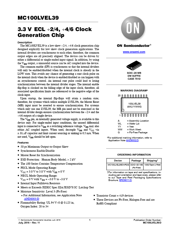
DESCRIPTION
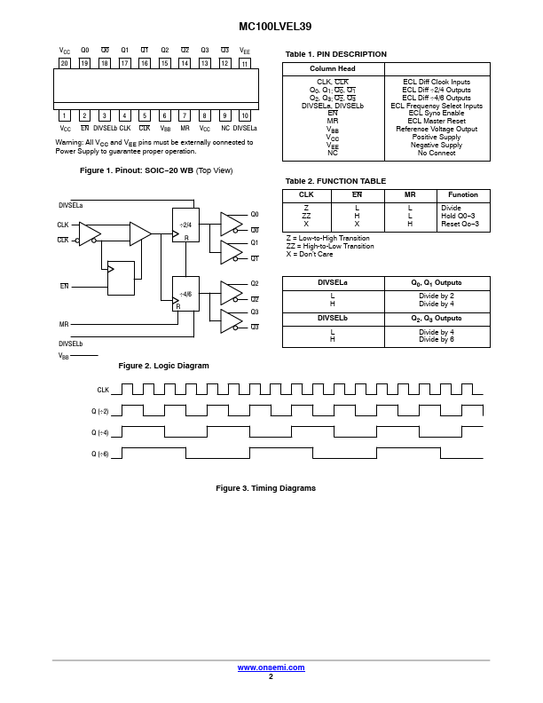
In addition, by using the VBB output, a sinusoidal source can be AC coupled into the device. The common enable (EN) is synchronous so that the internal dividers will only be enabled/disabled when the internal clock is already in the LOW state. This avoids any chance of generating a runt clock pulse on the internal clock when the device is enabled/disabled as can happen with an asynchronous control. An internal runt pulse could lead to losing synchronization between the internal divider stages. The internal enable flip-flop is clocked on the falling edge of the input clock, therefore, all associated specification limits are referenced to the negative edge of the clock input. Upon startup, the internal flip-flops will attain a random state; therefore, for systems which utilize multiple LVEL39s, the Master Reset (MR) input must be asserted to ensure synchronization. For systems which only use one LVEL39, the MR pin need not be exercised as the internal divider design ensures synchronization between the ÷2/4 and the ÷4/6 outputs of a single device. onsemi