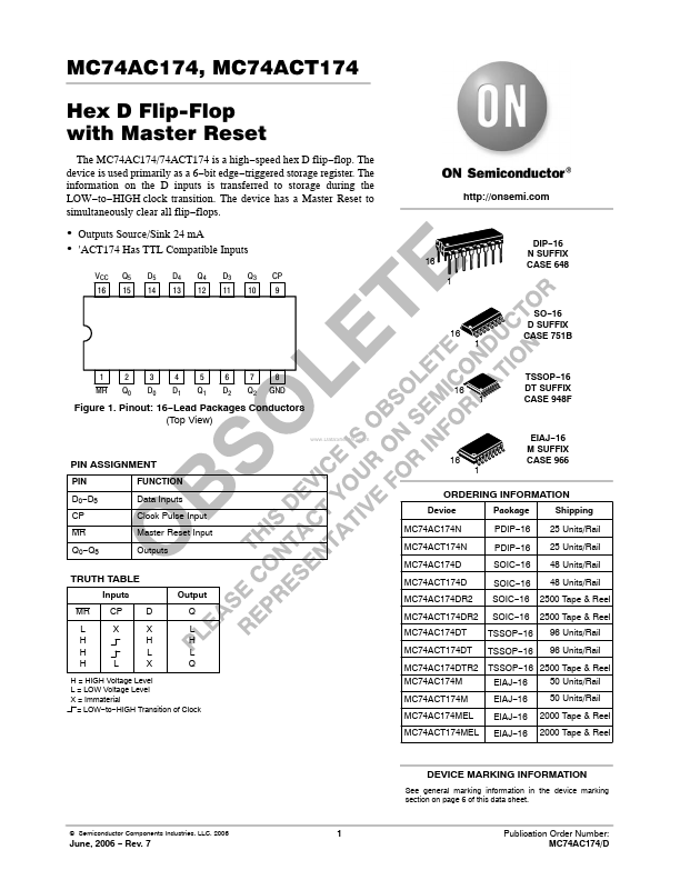
DESCRIPTION
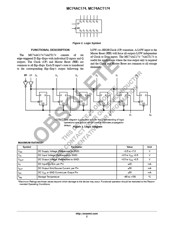
The MC74AC174/74ACT174 consists of six edge−triggered D flip−flops with individual D inputs and Q outputs. The Clock (CP) and Master Reset (MR) are common to all flip−flops. Each D input’s state is transferred to the corresponding flip−flop’s output following the MR CP D5 D4 D3 LOW−to−HIGH Clock (CP) transition. A LOW input to the Master Reset (MR) will force all outputs LOW independent of Clock or Data inputs. The MC74AC174/ 74ACT174 is useful for applications where the true output only is required and the Clock and Master Reset are common to all storage elements. D2 D1 D0 D CP CD Q D CP CD Q D CP CD Q D CP CD Q D CP CD Q D CP CD Q Q5 NOTE: Q4 Q3 Q2 Q1 Q0 This diagram is provided only for the understanding of logic operations and should not be used to estimate propagation delays. Figure 3. Logic Diagram MAXIMUM RATINGS
* Symbol VCC VIN VOUT IIN IOUT ICC Tstg Parameter DC Supply Voltage (Referenced to GND) DC Input Voltage (Referenced to GND) DC Output Voltage (Referenced to GND) DC Input Current, per Pin DC Output Sink/Source Current, per Pin DC VCC or GND Current per Output Pin Storage Temperature Value −0.5 to +7.0 −0. onsemi