onsemi NSBC114TF3
Digital Transistors
| Part No. | NSBC114TF3 |
|---|---|
| Datasheet | NSBC114TF3 Download |
| Manufacturer |  onsemi |
| Description | Digital Transistors |
| Buy | Stock & Price |
FEATURES
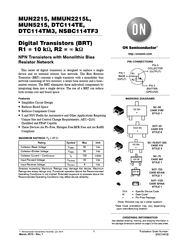
PIN 1 BASE (INPUT) PIN CONNECTIONS PIN 3 COLLECTOR (OUTPUT) R1 R2 PIN 2 EMITTER (GROUND)●
●
●
●
● MARKING DIAGRAMS SC−59 CASE 318D STYLE 1 Simplifies Circuit Design Reduces Board Space Reduces Component Count S and NSV Prefix for Automotive and Other
APPLICATIONS
Requiring Unique Site and Control Change Requirements; AEC−Q101 Qualified and PPAP Capable These Devices are Pb−Free, Halogen Free/BFR Free and are RoHS Compliant XX MG G 1 XXX MG G 1 SOT−23 CASE 318 STYLE 6MAXIMUM RATINGS
(TA = 25°C) Rating Collector−Base Voltage Collector−Emitter Voltage Collector Current − Continuous Input Forward Voltage Input Reverse Voltage Symbol VCBO VCEO IC VIN(fwd) VIN(rev) Max 50 50 100 40 6 Unit Vdc Vdc mAdc Vdc Vdc XX MG G 1 XX M 1 XX M 1 XM 1 XXX M G SC−70/SOT−323 CASE 419 STYLE 3 SC−75 CASE 463 STYLE 1 SOT−723 CASE 631AA STYLE 1 SOT−1123 CASE 524AA STYLE 1 Stresses exceedingMAXIMUM RATINGS
may damage the device.MAXIMUM RATINGS
are stress ratings only. Functional operation above the Recommended Operating Conditions is not implied.