DESCRIPTION
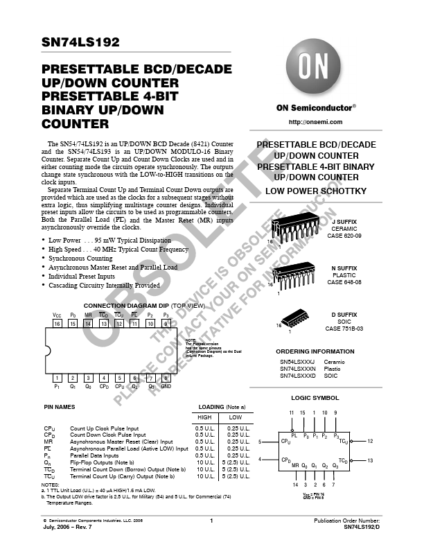
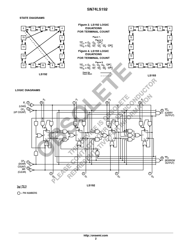
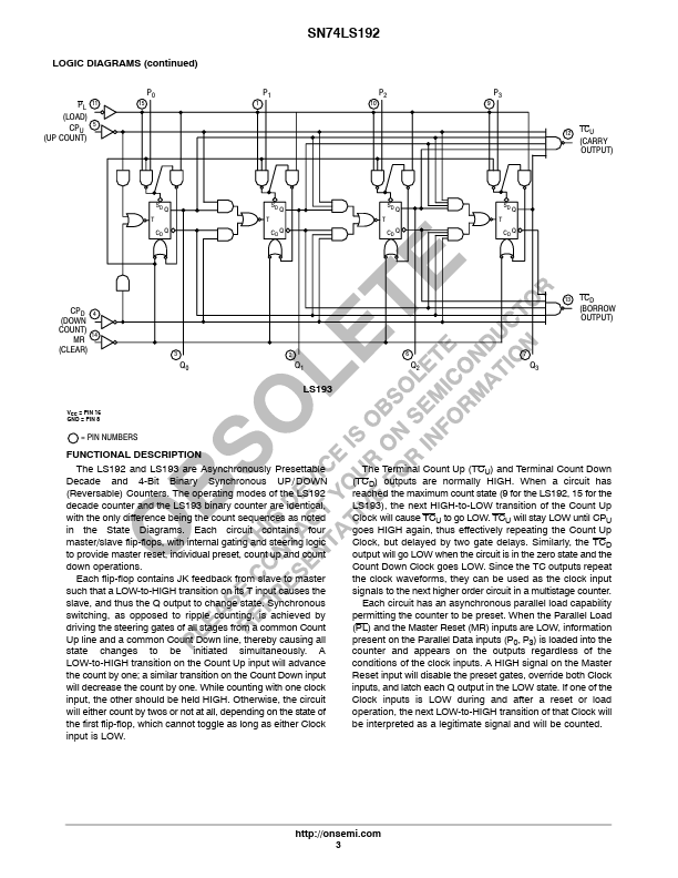
Each circuit contains four master/slave flip-flops, with internal gating and steering logic to provide master reset, individual preset, count up and count down operations. Each flip-flop contains JK feedback from slave to master such that a LOW-to-HIGH transition on its T input causes the slave, and thus the Q output to change state. Synchronous switching, as opposed to ripple counting, is achieved by driving the steering gates of all stages from a common Count Up line and a common Count Down line, thereby causing all state changes to be initiated simultaneously. A LOW-to-HIGH transition on the Count Up input will advance the count by one; a similar transition on the Count Down input will decrease the count by one. While counting with one clock input, the other should be held HIGH. Otherwise, the circuit will either count by twos or not at all, depending on the state of the first flip-flop, which cannot toggle as long as either Clock input is LOW. 13 TCD (BORROW OUTPUT) 67 Q2 Q3 The Terminal Count Up (TCU) and Terminal Count Down (TCD) outputs are normally HIGH. onsemi