DESCRIPTION
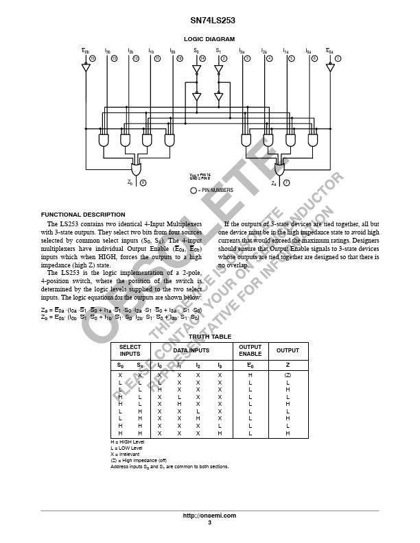
The LS253 contains two identical 4-Input Multiplexers with 3-state outputs. They select two bits from four sources selected by common select inputs (S0, S1). The 4-input multiplexers have individual Output Enable (E0a, E0b) inputs which when HIGH, forces the outputs to a high impedance (high Z) state. The LS253 is the logic implementation of a 2-pole, 4-position switch, where the position of the switch is determined by the logic levels supplied to the two select inputs. The logic equations for the outputs are shown below: Za = E0a ⋅(I0a ⋅S1 ⋅S0 + I1a ⋅S1 ⋅S0 ⋅I2a ⋅S1 ⋅S0 + I3a ⋅ S1 ⋅S0) Zb = E0b⋅ (I0b S1 S0 + I1b⋅ S1⋅ S0 I2b⋅ S1⋅ S0 + I3b⋅ S1⋅ S0) If the outputs of 3-state devices are tied together, all but one device must be in the high impedance state to avoid high currents that would exceed the maximum ratings. Designers should ensure that Output Enable signals to 3-state devices whose outputs are tied together are designed so that there is no overlap. TRUTH TABLE SELECT... onsemi