SOT23
SOT23 is SUGGESTED PAD LAYOUT manufactured by Diodes Incorporated.
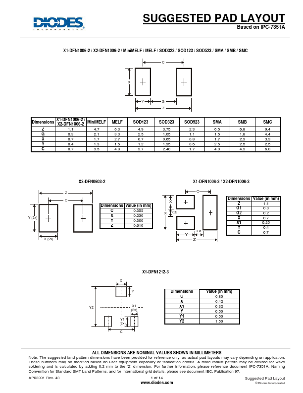
SUGGESTED PAD LAYOUT
Based on IPC-7351A
X1-DFN1006-2 / X2-DFN1006-2 / Mini MELF / MELF / SOD323 / SOD123 / SOD523 / SMA / SMB / SMC
Dimensions Z G X Y C
X1-DFN1006-2 / Mini MELF X2-DFN1006-2 1.1 4.7 0.3 2.1 0.7 1.7 0.4 1.3 0.7 3.5
MELF 6.3 3.3 2.7 1.5 4.8
SOD123 4.9 2.5 0.7 1.2 3.7
SOD323 3.75 1.05 0.65 1.35 2.40
SOD523 2.3 1.1 0.8 0.6 1.7
SMA 6.5 1.5 1.7 2.5 4.0
SMB 6.8 1.8 2.3 2.5 4.3
SMC 9.4 4.4 3.3 2.5 6.8
X3-DFN0603-2
.Data Sheet.net/
X1-DFN1006-3 / X2-DFN1006-3
C X1 X G2
Y (2x)
Dimensions Value (in mm) C 0.355 X 0.230 Y 0.300 Z 0.610
G1 Y
X (2x)
Dimensions Value (in mm) Z 1.1 G1 0.3 G2 0.2 X 0.7 X1 0.25 Y 0.4 C 0.7
X1-DFN1212-3
Y2 Y1 (2x) C
X1 (2x)
Dimensions C X X1 Y Y1 Y2
Value (in mm) 0.80 0.42 0.32 0.50 0.50 1.50
ALL DIMENSIONS ARE NOMINAL VALUES SHOWN IN MILLIMETERS Note: The suggested land pattern dimensions have been provided for reference only, as actual pad layouts may vary depending on application. These numbers may be modified based on user equipment capability or fabrication criteria. A more robust pattern may be desired for wave soldering and is calculated by adding 0.2 mm to the ‘Z’ dimension. For further information, please reference document IPC-7351A, Naming Convention for Standard SMT Land Patterns, and for International grid details, please see document IEC, Publication 97. AP02001 Rev. 43 1 of 14 .diodes. Suggested Pad Layout
© Diodes Incorporated
Datasheet pdf
- http://..co.kr/...