June 2013
MBR2535CT - MBR2560CT
25 A Schottky Barrier Rectifiers
Features
• Low Power Loss, High Efficiency
• High Surge Capacity
• Metal Silicon Junction, Majority Carrier Conduction
PIN1
• High Current Capacity, Low Forward Voltage Drop
PIN3
• Guard Ring for Over-Voltage Protection (OVP)
1
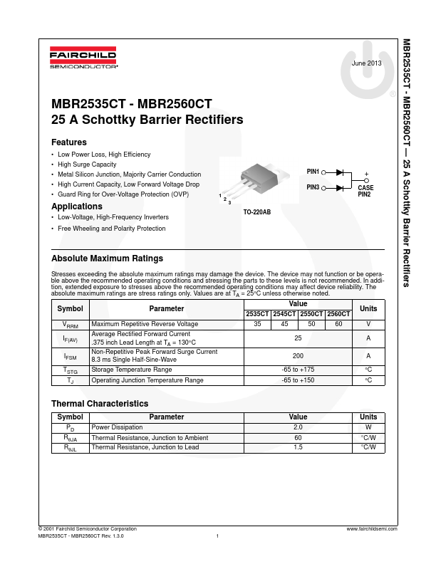
2
Applications
3
• Low-Voltage, High-Frequency Inverters
TO-220AB
• Free Wheeling and Polarity Protection
+
CASE
PIN2
Absolute Maximum Ratings
Stresses exceeding the absolute maximum ratings may damage the device. The device may not function or be opera-
ble above the recommended operating conditions and stressing the parts to these levels is not recommended. In addi-
tion, extended exposure to stresses above the recommended operating conditions may affect device reliability. The
absolute maximum ratings are stress ratings only. Values are at TA = 25°C unless otherwise noted.
Symbol
Parameter
Value
Units
2535CT 2545CT 2550CT 2560CT
VRRM
IF(AV)
IFSM
Maximum Repetitive Reverse Voltage
Average Rectified Forward Current
.375 inch Lead Length at TA = 130°C
Non-Repetitive Peak Forward Surge Current
8.3 ms Single Half-Sine-Wave
35
45
50
60
V
25
A
200
A
TSTG
TJ
Storage Temperature Range
Operating Junction Temperature Range
-65 to +175
°C
-65 to +150
°C
Thermal Characteristics
Symbol
PD
RθJA
RθJL
Parameter
Power Dissipation
Thermal Resistance, Junction to Ambient
Thermal Resistance, Junction to Lead
Value
2.0
60
1.5
Units
W
°C/W
°C/W
© 2001 Fairchild Semiconductor Corporation
MBR2535CT - MBR2560CT Rev. 1.3.0
1
www.fairchildsemi.com