Datasheet4U Logo Datasheet4U.com

IXYH40N90C3 - IGBT

Key Features

  • z Optimized for Low Switching Losses z Square RBSOA z Positive Thermal Coefficient of Vce(sat) z International Standard Package Advantages z High Power Density z Low Gate Drive Requirement Symbol Test Conditions (TJ = 25°C, Unless Otherwise Specified) BVCES IC = 250μA, VGE = 0V VGE(th) IC = 250μA, VCE = VGE ICES VCE = VCES, VGE = 0V TJ = 150°C IGES VCE = 0V, VGE = ±20V VCE(sat) IC = 40A, VGE = 15V, Note 1 TJ = 150°C Characteristic Values Min. Typ. Max. 950 V 3.5 5.5 V 25 μA.

📥 Download Datasheet

Full PDF Text Transcription (Reference)

The following content is an automatically extracted verbatim text from the original manufacturer datasheet and is provided for reference purposes only.

View original datasheet text
900V XPTTM IGBT GenX3TM High-Speed IGBT for 20-50 kHz Switching Preliminary Technical Information IXYH40N90C3 VCES = IC110 = V ≤CE(sat) tfi(typ) = 900V 40A 2.5V 110ns Symbol VCES VCGR VGES VGEM IC25 IC110 ICM SSOA (RBSOA) PC TJ TJM Tstg TL TSOLD Md Weight Test Conditions TJ = 25°C to 175°C TJ = 25°C to 175°C, RGE = 1MΩ Continuous Transient TC = 25°C TC = 110°C TC = 25°C, 1ms VGE = 15V, TVJ = 150°C, RG = 5Ω Clamped Inductive Load TC = 25°C Maximum Lead Temperature for Soldering 1.6 mm (0.062in.) from Case for 10s Mounting Torque Maximum Ratings 900 V 900 V ±20 V ±30 V 105 A 40 A 200 A ICM = 80 ≤@VCE VCES 600 A W -55 ... +175 175 -55 ... 
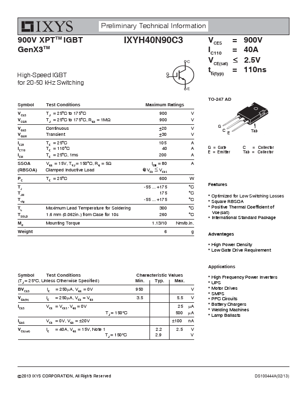
+175 °C °C °C 300 °C 260 °C 1.13/10 Nm/lb.in.