IXGQ20N120BD1 Overview
Key Specifications
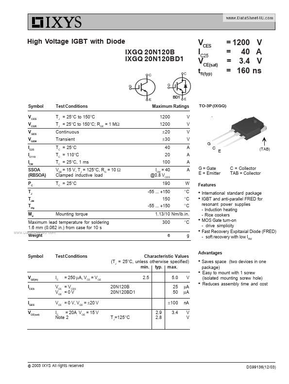
Mount Type: Through Hole
Pins: 3
Max Operating Temp: 150 °C
Min Operating Temp: -55 °C
Key Features
- C = Collector TAB = Collector Mounting torque 1.13/10 Nm/. 300 6
- Maximum lead temperature for soldering 1.6 mm (0.062 in.) from case for 10 s
- Weight International standard package IGBT and anti-parallel FRED for resonant power supplies
- Induction heating
- Rice cookers MOS Gate turn-on