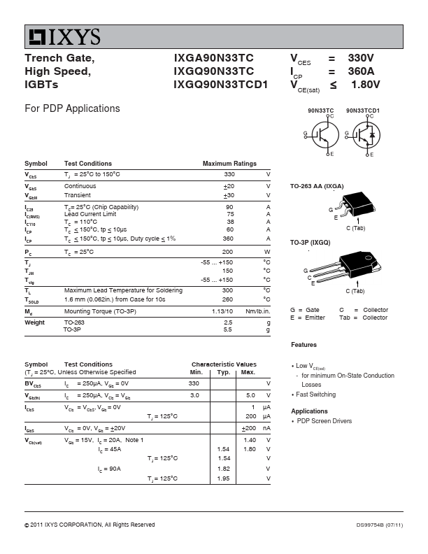
Datasheet4U Logo Datasheet4U.com

IXGQ90N33TC - IGBTs

Download the IXGQ90N33TC datasheet PDF (IXGA90N33TC included). The manufacturer datasheet provides complete specifications, pinout details, electrical characteristics, and typical applications for igbts.

Features

  • Symbol Test Conditions (TJ = 25°C, Unless Otherwise Specified BVCES VGE(th) ICES IGES VCE(sat) IC IC = 250μA, VGE = 0V = 250μA, VCE = VGE TJ = 125°C VCE = 0V, VGE = ±20V VGE = 15V, IC = 20A, Note 1 IC = 45A TJ = 125°C IC = 90A TJ = 125°C 1.54 1.54 1.82 1.95 Characteristic Values Min. Typ. Max. 330 3.0 5.0 1 200 ±200 1.40 1.80 V V μA μA nA V V V V V.
  • Low VCE(sat) - for minimum On-State Conduction Losses.
  • Fast Switching.

📥 Download Datasheet

Note: The manufacturer provides a single datasheet file (IXGA90N33TC-IXYSCorporation.pdf) that lists specifications for multiple related part numbers.
Other Datasheets by IXYS Corporation

Full PDF Text Transcription

Click to expand full text
Trench Gate, High Speed, IGBTs For PDP Applications IXGA90N33TC IXGQ90N33TC IXGQ90N33TCD1 VCES = ICP = VCE(sat) ≤ 90N33TC 330V 360A 1.80V 90N33TCD1 Symbol VCES VGES VGEM IC25 IC(RMS) IC110 ICP ICP PC TJ TJM Tstg TL TSOLD Md Weight Test Conditions TJ = 25°C to 150°C Continuous Transient TC= 25°C (Chip Capability) Lead Current Limit TC = 110°C TC < 150°C, tp < 10μs TC < 150°C, tp < 10μs, Duty cycle < 1% TC = 25°C Maximum Ratings 330 ±20 ±30 90 75 38 60 360 200 -55 ... +150 150 -55 ... +150 V V V A A A A A W °C °C °C °C °C Nm/lb.in. g g G = Gate E = Emitter G C E C (Tab) TO-263 AA (IXGA) G E C (Tab) TO-3P (IXGQ) Maximum Lead Temperature for Soldering 1.6 mm (0.062in.) from Case for 10s Mounting Torque (TO-3P) TO-263 TO-3P 300 260 1.13/10 2.5 5.
Published: |