Datasheet4U Logo Datasheet4U.com

IXSX50N60AU1S - IGBT

Download the IXSX50N60AU1S datasheet PDF. This datasheet also covers the IXSX50N60AU1 variant, as both devices belong to the same igbt family and are provided as variant models within a single manufacturer datasheet.

Features

  • l l l l Maximum lead temperature for soldering 1.6 mm (0.062 in. ) from case for 10 s l Hole-less TO-247 package for clip mounting High current rating Guaranteed Short Circuit SOA capability High frequency IGBT and antiparallel FRED in one package Low V CE(sat) - for minimum on-state conduction losses MOS Gate turn-on - drive simplicity Fast Recovery Epitaxial Diode (FRED) - soft recovery with low IRM Symbol Test Conditions Characteristic Values (TJ = 25° C, unless otherwise specified) mi.

📥 Download Datasheet

Note: The manufacturer provides a single datasheet file (IXSX50N60AU1_IXYSCorporation.pdf) that lists specifications for multiple related part numbers.

Full PDF Text Transcription (Reference)

The following content is an automatically extracted verbatim text from the original manufacturer datasheet and is provided for reference purposes only.

View original datasheet text
www.DataSheet4U.com Preliminary data IGBT with Diode Combi Pack Short Circuit SOA Capability VCES = 600 V IXSX50N60AU1 = 75 A IXSX50N60AU1S I C25 VCE(sat) = 2.7 V 
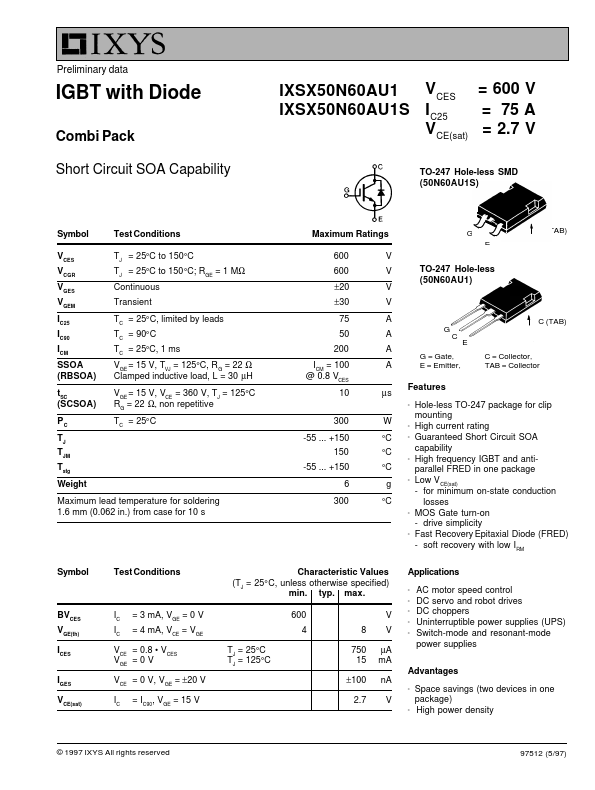
TO-247 Hole-less SMD (50N60AU1S) Symbol VCES VCGR VGES VGEM IC25 IC90 ICM SSOA (RBSOA) tSC (SCSOA) PC TJ TJM Tstg Weight Test Conditions TJ = 25°C to 150°C TJ = 25°C to 150 °C; RGE = 1 MΩ Continuous Transient TC = 25° C, limited by leads TC = 90° C TC = 25°C, 1 ms VGE = 15 V, TVJ = 125°C, R G = 22 Ω Clamped inductive load, L = 30 µH VGE = 15 V, VCE = 360 V, TJ = 125°C RG = 22 Ω, non repetitive TC = 25° C Maximum Ratings 600 600 ±20 ±30 75 50 200 ICM = 100 @ 0.8 VCES 10 300 -55 ... +150 150 -55 ...
Published: |