AUIRGP4062D-E
Key Features
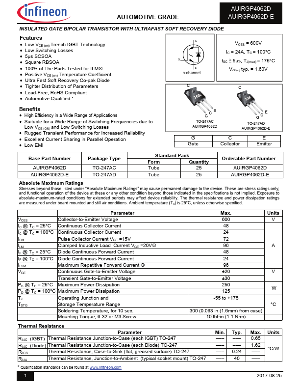
- Low VCE (on) Trench IGBT Technology
- Low Switching Losses
- Square RBSOA
- 100% of The Parts Tested for ILM
- Positive VCE (on) Temperature Coefficient
- Ultra Fast Soft Recovery Co-pak Diode
- Tighter Distribution of Parameters
- Lead-Free, RoHS compliant
- Automotive Qualified * C G E n-channel C VCES = 600V IC = 24A, TC = 100°C tSC 5µs, TJ(max) = 175°C VCE(on) typ. = 1.60V C Benefits
- High Efficiency in a Wide Range of Applications