IR3316S
Features
- -
- -
- -
- - Load current feedback Programmable over current shutdown Active clamp ESD protection Input referenced to Vcc Over temperature shutdown Switching time optimized for low EMI Reverse battery protection
Product Summary Rds(on) 7 mΩ max. Vcc op. 6 to 26V Current Ratio 8800 Prog. Ishutdown 10 to 90A Vclamp 40V Packages
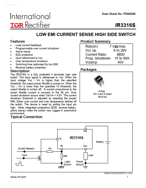
Description
The IR3316S is a fully protected 4 terminals high side switch. The input signal is referenced to Vcc. When the input voltage Vcc
- Vin is higher than the specified threshold, the output power Mosfet is turned on. When the Vcc
- Vin is lower than the specified Vil threshold, the output Mosfet is turned off. A current proportional to the power Mosfet current is sourced to the Ifb pin. Over current shutdown occurs when Vst-Vin > 4.5V. The current shutdown threshold is adjusted by selecting the proper RIfb. Either over current and over temperature latches off the switch. The device is reset by pulling the input pin high. Other integrated...