MBR2535CT-1 Description
/.
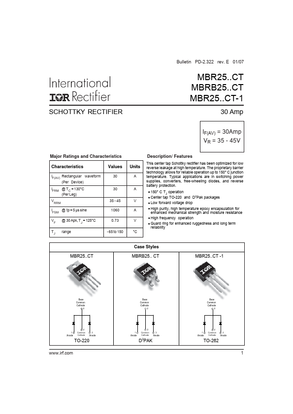
MBR2535CT-1 is SCHOTTKY RECTIFIER manufactured by International Rectifier.
| Part Number | Description |
|---|---|
| MBR2535CT | SCHOTTKY RECTIFIER |
| MBR2545CT | SCHOTTKY RECTIFIER |
| MBR2545CT-1 | SCHOTTKY RECTIFIER |
| MBR20 | SCHOTTKY RECTIFIER |
| MBR20080CT | SCHOTTKY RECTIFIER |
/.