KKA3010
KKA3010 is INFRARED REMOTE CONTROL TRANSMITTER RC-5 manufactured by Kodenshi AUK Group.
..
TECHNICAL DATA
INFRARED REMOTE CONTROL TRANSMITTER RC-5
The KKA3010 is intended as a general purpose (RC-5) infrared remote control system for use where a low voltage supply and a large debounce time are expected. The device can generate 2048 different mands and utilizes a keyboard with a single pole switch for each key. The mand are arranged so that 32 systems can be addressed, each system containing 64 different mands. The keyboard interconnection is illustrated by Fig.1.
- -
- -
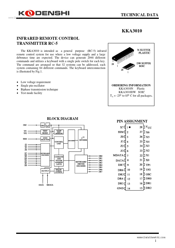
Low voltage requirement Single pin oscillator Biphase transmission technique Test mode facility
ORDERING INFORMATION KKA3010N Plastic KKA3010DW SOIC TA = -25° to 85° C for all packages.
BLOCK DIAGRAM
PIN ASSIGNMENT
..
PIN DESCRIPTION
PIN No 1 2 3-6 7 DESIGNATION X7 (IPU) SSM (I) Z0-Z3 (IPU) MDATA (OP3) DESCRIPTION sense input from key matrix system mode selection input sense inputs from key matrix generated output data modulated with 1/2 the oscillator frequency at a 25% duty factor generated output information scan drivers ground (0V) scan drivers oscillator input test point 2 test point 1 sense inputs from key matrix voltage supply
8 DATA (OP3) 9-13 DR7-DR3 (ODN) 14 GND 15-17 DR2-DR0 (ODN) 18 OSC (I) 19 TP2 (I) 20 TP1 (I) 21-27 X0-X6 (IPU) 28 Vcc (I) (I) = input (IPU) = input with p-channel pull-up transistor (ODN) = output with open drain n-channel transistor (OP3) = output 3-state
FUNCTIONAL DESCRIPTION Keyboard operation Every connection of one X-input and one DR-output will be recognized as a legal key operation and will cause the device to generate the corresponding code. The same applies to every connection of one Z-input to one DR-output with the proviso that SSM must be LOW. When SSM is HIGH a wired connection must exist between a Z-input and DRoutput. If no connection is present the system number will not be generated. Activating two or more X-inputs, Z-inputs or Z-inputs and X-inputs at the same time...