C106B Overview
Key Specifications
Description
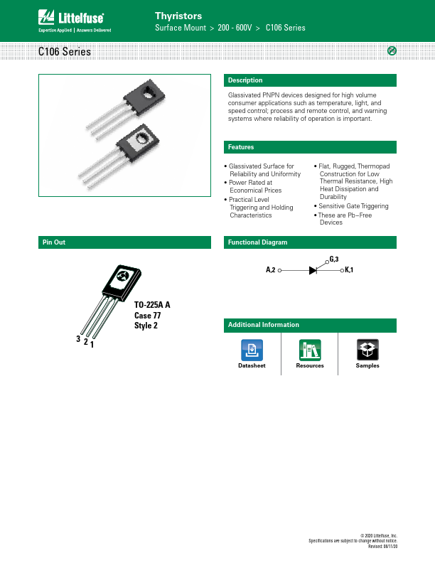
Glassivated PNPN devices designed for high volume consumer applications such as temperature, light, and speed control; process and remote control, and warning systems where reliability of operation is important.
Key Features
- Glassivated Surface for Reliability and Uniformity
- Power Rated at Economical Prices
- Practical Level Triggering and Holding Characteristics
- Flat, Rugged, Thermopad Construction for Low - Sensitive Gate Triggering