MAX5270
Overview
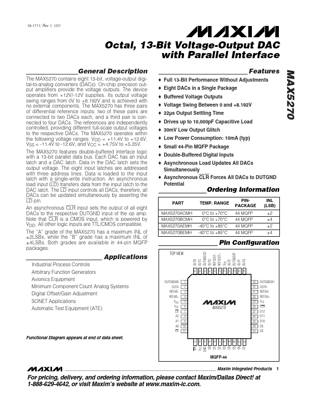
The MAX5270 contains eight 13-bit, voltage-output digital-to-analog converters (DACs). On-chip precision output amplifiers provide the voltage outputs.
| Part | MAX5270 |
|---|---|
| Description | Octal / 13-Bit Voltage-Output DAC with Parallel Interface |
| Manufacturer | Maxim Integrated |
| Size | 251.41 KB |
The MAX5270 contains eight 13-bit, voltage-output digital-to-analog converters (DACs). On-chip precision output amplifiers provide the voltage outputs.
| Part Number | Manufacturer | Description |
|---|---|---|
| AN214 | Microchip Technology | Smart Transducer Interface |
| XT2052 | Silinktek | 1A Is Compatible With the USB Interface Linear Battery Management |
| AiP650E | I-CORE | 2-line Serial Interface/Common Cathode 8Seg 4Grid LED Controller/Driver |